RadiMation Application Note 167
Controlling a custom relay via the Configurable Switch Matrix driver[edit]
This application note explains how a user-made Arduino device that controls a relay can be operated directly from RadiMation® by using the Configurable Switch Matrix device driver. By configuring the correct serial communication and defining the proper commands, it is possible to automatically switch between a low-frequency and a high-frequency amplifier within the Radiated Immunity module — without the need for a dedicated device driver.
Introduction[edit]
In automated EMC test systems it is often necessary to switch between different signal paths, for example between amplifiers that cover different frequency ranges. RadiMation® includes built-in support for many switch matrix devices, but there may be situations where a user builds a simple control unit such as an Arduino-based relay controller.
Even if no specific device driver exists, the Arduino can still be controlled from RadiMation® through the Configurable Switch Matrix driver. This application note describes how to configure two drivers (one for a low-frequency and another for the high-frequency amplifier), how to set up serial communication, and how to integrate the devices in a test-site configuration.
Hardware setup[edit]
Arduino device[edit]
The custom device is an Arduino microcontroller connected to the PC through a serial (RS232) interface at 115200 baud. It reacts to simple ASCII commands:
ID?=> returns the textAMPSwitcher v1.0LOW_FREQ_AMP=> connects the low-frequency amplifier to the antennaHIGH_FREQ_AMP=> connects the high-frequency amplifier to the antenna
The Arduino does not reply with acknowledgements such as “OK” or “ERROR”; it simply executes the relay switching upon receiving the command.
System integration[edit]
In a typical radiated immunity test setup, two amplifiers are connected to one antenna:
- Low-frequency amplifier, usable in the frequency range 80 MHz – 1 GHz
- High-frequency amplifier, usable in the frequency range 1 GHz – 3 GHz
The Arduino relay selects which amplifier output is routed to the antenna. By configuring RadiMation® to send the appropriate command automatically, switching between amplifiers becomes fully automated.
For a general explanation of using switch matrices in RadiMation®, refer to Application Note 123: Implementing the control of a switch matrix in RadiMation®.
Driver configuration in RadiMation[edit]
Creating a driver for the low-frequency amplifier[edit]
- In RadiMation®, open the menu
-
 Configuration
- Configuration
- Device Drivers
-
-
-
- Choose the device type Switch matrixes and click on Add.
- From the list, select the Configurable Switch Matrix.
- Set the description to the state that is actually being selected by the driver for example:
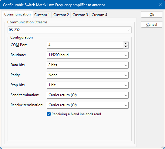
Low-Frequency amplifier to antenna. - Open the Advanced driver configuration and go to the Communication tab.
- Select RS-232 as the communication stream.
- Configure the correct COM port and set the baud rate to 115200 baud.
- Ensure the data format matches the Arduino settings (typically 8 data bits, no parity, 1 stop bit).
- Select the Custom 1 tab and configure:
- Get ID command:
ID? - Expected ID string:
AMPSwitcher v1.0 - During Test command:
LOW_FREQ_AMP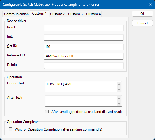
- Get ID command:
- Close the advanced driver configuration.


Creating a driver for the high-frequency amplifier[edit]
Repeat the above procedure to create a second driver.
Use a description such as High-Frequency amplifier to antenna and configure the During Test command to be HIGH_FREQ_AMP.
All other parameters, including the communication settings and identification command, remain the same.

Integration in the Test-Site[edit]
Once both Configurable Switch Matrix drivers are created, they can be added to the appropriate test-site so that the correct relay is activated automatically.
- Open the menu
- Configuration
- Test Sites .
-
-
- Select or create the relevant test-site for your Radiated Immunity measurement.
- Add the switch matrix device drivers to the test-site configuration.
- For the low-frequency testsite, select the switch matrix driver
Low-Frequency amplifier to antenna. - For the high-frequency testsite, select the driver
High-Frequency amplifier to antenna. - When a test is executed, RadiMation® automatically sends the configured
LOW_FREQ_AMPorHIGH_FREQ_AMPcommand during the initialisation of the test. - If multiple relays are used, you can either create additional configurable switch matrix drivers or extend a single driver with multiple commands.
For additional information on how switch matrices are used in test-sites, please see Application Note 123: Implementing the control of a switch matrix in RadiMation® which explains this in more detail.
Conclusion[edit]
Even a home-made or unsupported switching device can be operated within RadiMation® by means of the Configurable Switch Matrix driver.
By correctly defining the serial settings and the necessary commands (ID?, LOW_FREQ_AMP, HIGH_FREQ_AMP), the Arduino device will be recognised and controlled automatically during the test sequence.
This approach provides an easy way to extend automation and flexibility in EMC test setups without requiring any custom driver development.