Chapter 4: Difference between revisions
| (127 intermediate revisions by 6 users not shown) | |||
| Line 1: | Line 1: | ||
__NOTOC__ | __NOTOC__ | ||
=Radiated immunity= | = Radiated immunity = | ||
Radiated immunity test are a simulation of R.F. fields generated by strong transmitters as walky-talkies, mobile phones, porto-phones and broadcast transmitters. | Radiated immunity test are a simulation of R.F. fields generated by strong transmitters as walky-talkies, mobile phones, porto-phones and broadcast transmitters. | ||
During radiated immunity tests, a RF field is generated in the test | During radiated immunity tests, a RF field is generated in the test [[anechoic chamber]]. Different [[EMC]] [[standard]]s use different methods to generate this field. The {{RadiMation}} test software supports the following four different methods for radiated immunity tests: | ||
*Substitution method | *Substitution method | ||
*Field | *Field leveling method | ||
*Fixed generator method | *Fixed generator method | ||
*Performance level method | *Performance level method | ||
For more information, please read the chapters | For more information, please read the chapters 'Substitution test method', 'Fixed Field test method', 'Fixed Power test method' and 'Minimum performance test method', Each test method has it’s own benefits and draw backs. | ||
[[Image:Radiated Immunity Substitution Test Window.png]] | |||
== Substitution test method == | |||
==Substitution method== | |||
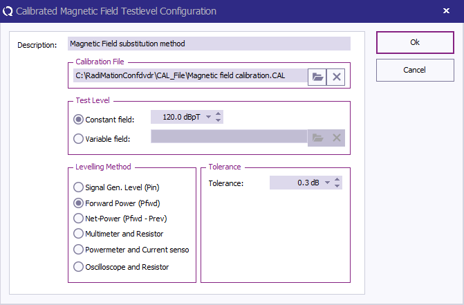
To perform radiated immunity tests according to the substitution' method, the empty anechoic chamber is first calibrated. The calibration file is then used generate the same power into the transmitting antenna as was needed during the calibration, to achieve the desired field strength (with the EUT in the anechoic chamber). | |||
[[Image:Menu Tests Radiated Immunity Substitution.png]] | |||
For immunity tests according to IEC 1000-4-3, normally a shielded, full anechoic chamber is used. The chamber must have a minimum of 1.5 * 1.5 m | For immunity tests according to IEC 1000-4-3, normally a shielded, full anechoic chamber is used. The chamber must have a minimum of 1.5 m * 1.5 m square homogeneous field area in front of the transmitting antenna. | ||
The transmitting antenna should be preferable at a distance of 3 meters from the Equipment Under Test. Before actual tests can take place, calibration of the test set-up is required. See the chapter on Calibration for more information about the method for a 1-point calibration, and the method used for a 16-point field homogeneity check as required by IEC 1000-4-3. | The transmitting antenna should be preferable at a distance of 3 meters from the Equipment Under Test. Before actual tests can take place, calibration of the test set-up is required. See the chapter on Calibration for more information about the method for a 1-point calibration, and the method used for a 16-point field homogeneity check as required by IEC 1000-4-3. | ||
| Line 30: | Line 35: | ||
The calibration files are downwards compatible. This means that a Net power calibration file can be used to perform a Forward power or signal generator level test and a Forward power calibration file can be used to perform a signal generator level test. | The calibration files are downwards compatible. This means that a Net power calibration file can be used to perform a Forward power or signal generator level test and a Forward power calibration file can be used to perform a signal generator level test. | ||
The recorded value is the value necessary to generate a constant field in the anechoic chamber. For example, if a test level of 10 V/m has to be generated, the generated field in the anechoic chamber must be 10 V/m (- 0 dB + 6 dB) on 75% of the 16 test points in the 1.5 * 1.5 m | The recorded value is the value necessary to generate a constant field in the anechoic chamber. For example, if a test level of 10 V/m has to be generated, the generated field in the anechoic chamber must be 10 V/m (- 0 dB + 6 dB) on 75% of the 16 test points in the 1.5 m * 1.5 m area (See Calibration). | ||
After the test set-up has been calibrated, tests can be performed using the calibration file. Care should be taken for selecting the correct calibration file. The calibration file(s) for horizontal and vertical antenna polarization are quite often different. Chamber characteristics and dimensions cause these differences. | |||
=== Benefits === | |||
Substitution method tests have a high level of reproducibility. In contradiction to the field leveling method no correction is made for the influence on the field strength caused by the EUT. | |||
Substitution | [[Image:Graph Radiated Immunity Substitution Test.png]] | ||
[[Image:Radiated Immunity Test Setup Substitution.png]] | |||
{|class="wikitable" | |||
!# ||Device name || Tab in {{Radimation}} configuration window | |||
|- | |||
| ||Signal Generator || Devices 1 | |||
|- | |||
| || Amplifier || Devices 1 | |||
|- | |||
| ||Coupler || Devices 1 | |||
|- | |||
| ||Forward Power meter || Devices 1 | |||
|- | |||
| ||Reflected Power meter Pref || Devices 1 | |||
|- | |||
| ||Antenna || Devices 1 | |||
|- | |||
!colspan="3"|Cables | |||
|- | |||
|1 || Cable SG -> amplifier || Cables | |||
|- | |||
|2 || Cable amplifier -> coupler || Cables | |||
|- | |||
|3 || Cable coupler -> antenna || Cables | |||
|- | |||
|4 || Cable coupler -> refl power meter || Cables | |||
|- | |||
|5 || Cable couper -> fwd power meter || Cables | |||
|} | |||
Note | {{Note|Usage of cable correction factors is not mandatory. However, using correction factors will increase measurement accuracy during immunity measurements. | ||
Usage of cable correction factors is not | |||
correction factors will increase measurement | |||
measurements. | |||
Although, during immunity measurements according to the substitution method, | Although, during immunity measurements according to the substitution method, cable correction factors will increase the accuracy of measured/displayed power values. The generated field accuracy will however be the same when using correction factors or not. | ||
cable correction factors will increase the accuracy of measured/displayed | |||
power values. The generated field accuracy will however be the same when | |||
using correction factors or not. | |||
When in doubt contact your reseller. | When in doubt contact your reseller. | ||
}} | |||
=== Configuration window === | |||
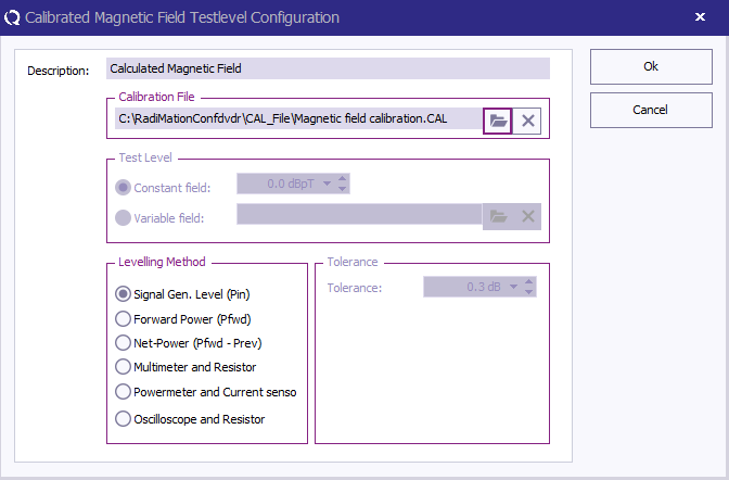
The (substitution) configuration window looks as followed: | |||
[[Image:Radiated Immunity Substitution Configuration Window.png]] | |||
*'''Dwell Time:''' The dwell time is applied after the levelling routine has finished. | |||
**'''Fixed dwell time:''' The fixed dwell time is a fixed time period. | |||
**'''External:''' The external dwell time can be used with an external EUT controller. {{RadiMation}} asks the EUT controller is the dwell time is finished. The EUT controller is determining if the dwell time has finished. | |||
== Fixed Power test method == | |||
=Fixed | |||
Fixed generator tests can be useful during various kinds of EMC tests. During current injection tests, this method can be used to achieve the maximum injected current the amplifier is able to generate. Although this will not be a constant current over the frequency range, it can be useful during engineering work. | Fixed generator tests can be useful during various kinds of EMC tests. During current injection tests, this method can be used to achieve the maximum injected current the amplifier is able to generate. Although this will not be a constant current over the frequency range, it can be useful during engineering work. | ||
| Line 116: | Line 106: | ||
#Tests with a fixed transmitted power level take cable losses, amplifier frequency response and VSWR mismatch into account. Two power meters are required during these tests, one to measure the forward power, and one to measure the reflected power. The difference between forward power and reflected power is the transmitted power. | #Tests with a fixed transmitted power level take cable losses, amplifier frequency response and VSWR mismatch into account. Two power meters are required during these tests, one to measure the forward power, and one to measure the reflected power. The difference between forward power and reflected power is the transmitted power. | ||
[[Image:Menu Tests Radiated Immunity Fixed Power.png]] | |||
[[Image:Radiated Immunity Test Setup Fixed Power.png]] | |||
Device name Tab in Radimation configuration window | {|class="wikitable" | ||
Signal Generator | ! # || Device name || Tab in {{Radimation}} configuration window | ||
Amplifier | |- | ||
Coupler | | ||Signal Generator || Devices 1 | ||
Power meter | |- | ||
Power meter | | ||Amplifier || Devices 1 | ||
Antenna | |- | ||
| ||Coupler || Devices 1 | |||
|- | |||
| ||Forward Power meter || Devices 1 | |||
|- | |||
| ||Reflected Power meter || Devices 1 | |||
|- | |||
| ||Antenna || Devices 1 | |||
|- | |||
!colspan="3"|'''Cables''' | |||
|- | |||
|1 || cable sg -> Amplifier || Cables | |||
|- | |||
|2 || cable amplifier -> Coupler || Cables | |||
|- | |||
|3 ||cable coupler -> Antenna || Cables | |||
|- | |||
|4 ||cable coupler -> fwd power meter || Cables | |||
|- | |||
|5 ||cable Couper -> refl || Cables | |||
|} | |||
Note | {{Note| Usage of cable correction factors is not mandatory. However, using correction factors will increase measurement accuracy during immunity measurements. | ||
Usage of cable correction factors is not | |||
correction factors will increase measurement | |||
measurements. | |||
When in doubt contact your reseller. | When in doubt contact your reseller. | ||
}} | |||
== Fixed Field test method == | |||
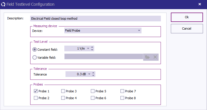
During Radiated immunity tests according to the “field leveling” method, the generated field during the test is real time leveled to the desired value. For “Field leveling” tests, no calibration files are required. Some EMC standards, like automotive standards, describe field leveling test methods. | |||
[[Image:Menu Tests Radiated Immunity Fixed Field.png]] | |||
[[Image:Radiated Immunity Test Setup Fixed Field.png]] | |||
{|class="wikitable" | |||
! #||Device name || Tab in {{Radimation}} configuration window | |||
|- | |||
| ||Signal Generator || Devices 1 | |||
|- | |||
| ||Amplifier || Devices 1 | |||
|- | |||
| ||Coupler || Devices 1 | |||
|- | |||
| ||Forward Power meter || Devices 1 | |||
|- | |||
| ||reflected Power meter || Devices 1 | |||
|- | |||
| ||Antenna || Devices 1 | |||
|- | |||
| ||Field sensor || Field probes | |||
|- | |||
!colspan="3"|'''Cables''' | |||
|- | |||
|1 || cable sg -> amplifier || Cables | |||
|- | |||
|2 || cable amplifier -> coupler || Cables | |||
|- | |||
|3 || cable coupler -> antenna || Cables | |||
|- | |||
|4 || cable coupler -> fwd power meter || Cables | |||
|- | |||
|5 || cable coupler -> refl power meter || Cables | |||
|} | |||
{{Note|Usage of cable correction factors is not mandatory. However, using correction factors will increase measurement accuracy during immunity measurements. | |||
When in doubt contact your reseller. | |||
}} | |||
== Triplate test method == | |||
The triplate test is a substitution test, based on a triplate calibration. The triplate test is almost the same as the substitution test. The major difference is the amount of points and the determination of the needed power. The triplate impedance is determined during the calibration, using 5 calibrations. | The triplate test is a substitution test, based on a triplate calibration. The triplate test is almost the same as the substitution test. The major difference is the amount of points and the determination of the needed power. The triplate impedance is determined during the calibration, using 5 calibrations. | ||
To calculate the required power the following formula is used: | To calculate the required power the following formula is used: | ||
<math>P_{mid}(f)[W]=\frac{E_v(f)^2*h^2}{Z(f)}</math> | |||
Formula 4 1 | {{Formula|4|1}} | ||
where | where | ||
<math>P_{mid}(f)[W]=\frac{P_{net}[W] + P_{out}[W]}{2}</math> | |||
Formula 4 2 | {{Formula|4|2|Calculation of middle power}} | ||
To configure a triplate test you need to open the configuration window. | To configure a triplate test you need to open the configuration window. | ||
[[Image:Menu Tests Radiated Immunity Triplate.png]] | |||
In the configuration window, you need to specify the calibration file you wish to use. Please note that it is possible to select a five-point calibration file as well as a one-point calibration. This is done so that you can verify your one point calibration. Don’t forget to define the following points: | In the configuration window, you need to specify the calibration file you wish to use. Please note that it is possible to select a five-point calibration file as well as a one-point calibration. This is done so that you can verify your one point calibration. Don’t forget to define the following points: | ||
* Testlevel | |||
* Dwelltime | |||
* Antenna distance, in our case the triplate | |||
* Amplifier protection | |||
Press the Start test button to start the test. | Press the Start test button to start the test. | ||
[[Image:Radiated Immunity Test Setup Triplate.png]] | |||
Device name Tab in Radimation configuration window | |||
Signal Generator | {|class="wikitable" | ||
Amplifier | ! # ||Device name || Tab in {{Radimation}} configuration window | ||
Coupler | |- | ||
Power meter | | ||Signal Generator || Devices 1 | ||
Power meter | |- | ||
Antenna | | ||Amplifier || Devices 1 | ||
Output coupler | |- | ||
Output power meter | | ||Coupler || Devices 1 | ||
|- | |||
| ||Forward Power meter || Devices 1 | |||
|- | |||
| ||Reflected Power meter || Devices 1 | |||
|- | |||
| ||Antenna || Devices 1 | |||
|- | |||
| ||Output coupler || Devices 2 | |||
|- | |||
| ||Output power meter || Devices 2 | |||
|- | |||
!colspan="3" |'''Cables''' | |||
|- | |||
|1 || cable sg -> amplifier || Cables | |||
|- | |||
|2 || cable amplifier -> coupler || Cables | |||
|- | |||
|3 || cable coupler -> antenna || Cables | |||
|- | |||
|4 || cable coupler -> fwd power meter || Cables | |||
|- | |||
|5 || cable coupler -> refl power meter || Cables | |||
|- | |||
|6 || cable triplate -> coupler || Cables | |||
|- | |||
|7 || cable coupler -> output power meter || Cables | |||
|} | |||
Note | {{Note|Usage of cable correction factors is not mandatory. However, using correction factors will increase measurement accuracy during immunity | ||
Usage of cable correction factors is not | |||
correction factors will increase measurement | |||
measurements. | measurements. | ||
When in doubt contact your reseller. | When in doubt contact your reseller. | ||
}} | |||
==Frequency | == Frequency Change Mode test methods == | ||
Most EMC standards do not describe if, or how the RF signal must be switched on and off between the test frequencies. | |||
In real world situations, transitions in RF fields occur quite often. For example, switching on a hand held transmitter or mobile phone would give a transition in the RF field. For this reason, if the used test standard does not prescribe a defined method to handle the field between test points, we recommend to use the “stress tested” method. During this test method, the RF signal is switched on and off between each test point. | |||
{{RadiMation}} supports four different ways to generate the RF signal between test frequencies. These four methods can be used during substitution, current leveling, fixed generator and minimum performance level tests. For more information on these methods, see the paragraphs: | |||
* {{ScreenElement|Stress test}} method | |||
* {{ScreenElement|Ramp}} method | |||
* {{ScreenElement|Constant}} method | |||
* {{ScreenElement|Fast Constant}} method | |||
Next to these 'standard' test methods {{RadiMation}} supports the so-called minimum performance method described in paragraph 3.4.6. | |||
[[Image:Frequency Mode Stress Ramp Constant Fast Constant.png]] | |||
=== Stress test method === | |||
During the stress test method, The RF test signal is switched on and off between test points. Transients in the RF field can cause great influence on electronic equipment, where a constant RF field with the same amplitude, does not have any influence. | |||
The “stress tested” test method therefore is a worst case test method, which is not required for all EMC standards. However, since this test method simulates the real world situation in the best way, we recommend using this method as the standard method, unless there is a very good reason to test the EUT with another method. | |||
=== Ramp method === | |||
During the Ramp method, for each test point, the RF signal is ramped up from a level below the required level. The ramp up and ramp down time, as well as the attenuation, is software configurable. After testing for a period of the “Dwell time”, the RF signal is ramped down to a level of below the test level. | |||
{{ReportGeneratorInfo|For more information on how to use the frequency change mode: Ramp in Multi Band Tests, see https://wiki.radimation.com/wiki/index.php/Radimation_Application_Note_134}} | |||
=== Constant method === | |||
=== | |||
During the | During the constant method, the RF field is kept constant as good as possible (i.e. the field is not switched off between test point). Of course, any test set-up (signal generator, amplifier, anechoic cabling and injection clamp) will have a frequency response, which is not completely flat. Because of this frequency response, switching between frequency points will always give a slight change in RF level. | ||
Depending on the frequency response, the gain of the system for the next frequency point can be greater or smaller than the gain of the previous frequency point. | Depending on the frequency response, the gain of the system for the next frequency point can be greater or smaller than the gain of the previous frequency point. | ||
To avoid positive RF level transitions during frequencies changes (which will have over testing as a result) the software determines if the drive level for the next frequency point is higher or lower than the drive level of the current frequency point. If the drive level for the next frequency point is lower, first the amplitude is decreased and then the frequency is incremented. | To avoid positive RF level transitions during frequencies changes (which will have over testing as a result) the software determines if the drive level for the next frequency point is higher or lower than the drive level of the current frequency point. If the drive level for the next frequency point is lower, first the amplitude is decreased and then the frequency is incremented. | ||
However, if the drive level for the next frequency point is higher, first the frequency is increased and then the amplitude is increased. | However, if the drive level for the next frequency point is higher, first the frequency is increased and then the amplitude is increased. The dwell time starts after the correct power level has been reached, and modulation when configured is applied. | ||
=== | === Fast constant method === | ||
As for the | As for the constant method, during the fast constant method, the RF field is kept constant as good as possible (i.e. the field is not switched off between test point). | ||
In contradiction to the constant field method, the modulation is not switched on and | In contradiction to the constant field method, the modulation is not switched on and off during the test. This means that the software measures power and field with the modulation switched on. | ||
The software will correct for measurement errors due to the modulation. Although this will result in slightly higher test errors, no transients in the RF field will occur caused by modulation switching. This test method will be faster than constant field-testing caused by the lack of | The software will correct for measurement errors due to the modulation. Although this will result in slightly higher test errors, no transients in the RF field will occur caused by modulation switching. This test method will be faster than constant field-testing caused by the lack of leveling time. | ||
Depending on the quality of the test equipment and the frequency step size, the amplitude of the test signal will slightly change. | Depending on the quality of the test equipment and the frequency step size, the amplitude of the test signal will slightly change. | ||
Using a small step size will | Using a small step size will minimize this problem. Due to the method described above, during the constant field method, over testing does not occur. | ||
Note | {{Note|Powermeter that are not using an RMS detector, should not be used in combination with Fast constant mode}} | ||
Powermeter | |||
===Minimum performance Method=== | === Minimum performance Method === | ||
The | The {{RadiMation}} package also supports a specific method to determine the minimum performance level of a Equipment Under Test. This method differentiates itself from the aforementioned methods that is does not generate a fixed specified field strength but a varying field strength based on the susceptibility of the Device Under Test. | ||
The method relies heavily on EUT monitoring (see chapter 8) to determine at which level the | The method relies heavily on EUT monitoring (see [[chapter 8]]) to determine at which level the [[Equipment Under Test]] is influenced. Before the test is started the relevant A/D-channels have to be configured. Pushing the input button on the configuration screen does this. | ||
The test is started at a (low) field strength level after which the field strength is increased with a specified increment till either of both situations arises. The field strength is limited by amplifier protection or the | The test is started at a (low) field strength level after which the field strength is increased with a specified increment till either of both situations arises. The field strength is limited by amplifier protection or the Equipment Under Test will be influenced in such way that the specified limits are exceeded. The field strength is than reduced with a specified step and the software will change to the next frequency point. This test will result in a graph showing the level to which the Equipment Under Test is unaffected by a radiated field. | ||
==Calibration methods== | == Calibration methods == | ||
===Signal generator level calibration=== | |||
=== Signal generator level calibration === | |||
During signal generator level calibration only the signal generator level is recorded during the calibration. During a signal generator power substitution test, the signal generator level to input of the amplifier, is kept the same as recorded during the calibration. | During signal generator level calibration only the signal generator level is recorded during the calibration. During a signal generator power substitution test, the signal generator level to input of the amplifier, is kept the same as recorded during the calibration. | ||
This method does not take amplifier instability into account. During this calibration method, no power meters are required. This method is less accurate than the FWD power and transmitted power calibrations and therefore not recommended for full compliance tests. | This method does not take amplifier instability into account. During this calibration method, no power meters are required. This method is less accurate than the FWD power and transmitted power calibrations and therefore not recommended for full compliance tests. | ||
During a signal level calibration, the field strength during calibration is recorded. | During a signal level calibration, the field strength during calibration is recorded. | ||
===Forward power calibration=== | |||
=== Forward power calibration === | |||
During a Forward power calibration, the forward power to the transmitting antenna is recorded. During a forward power substitution test, the FWD power to the antenna is kept the same as during the calibration. By this method, amplifier drift will have no influence on the test. | During a Forward power calibration, the forward power to the transmitting antenna is recorded. During a forward power substitution test, the FWD power to the antenna is kept the same as during the calibration. By this method, amplifier drift will have no influence on the test. | ||
When a forward calibration is made, this calibration file can also be used to perform a signal generator substitution test. | When a forward calibration is made, this calibration file can also be used to perform a signal generator substitution test. | ||
During a forward power calibration, the signal generator level and the field strength during calibration is recorded. | During a forward power calibration, the signal generator level and the field strength during calibration is recorded. | ||
===Net power calibration=== | |||
=== Net power calibration === | |||
During a net power calibration, the forward and reflected power to the antenna is recorded. The difference between the forward power and reflected power is the net power. | During a net power calibration, the forward and reflected power to the antenna is recorded. The difference between the forward power and reflected power is the net power. | ||
| Line 276: | Line 336: | ||
During a forward power calibration, the signal generator level, forward power level and the field strength during calibration is recorded. | During a forward power calibration, the signal generator level, forward power level and the field strength during calibration is recorded. | ||
== Modulation == | |||
=== Amplitude Modulation (AM) === | |||
=== | |||
During most radiated and conducted immunity tests, the test signal must be Amplitude Modulated. If a modulation is chosen, this modulation will only be switched on during the period of the dwell time. In between test points, when the test signal is set to the next frequency point, the modulation is switched off. | During most radiated and conducted immunity tests, the test signal must be Amplitude Modulated (AM). If a modulation is chosen, this modulation will only be switched on during the period of the dwell time. In between test points, when the test signal is set and adjusted to the next frequency point, the modulation is switched off. | ||
The reason for this is that measurements of the field or current, with the modulation switched on, are less accurate than without modulation. This is essentially important during real time | The reason for this is that measurements of the field or current, with the modulation switched on, are less accurate than without modulation. This is essentially important during real time leveled tests. Dependent on the capabilities of the signal generator used, internal and external modulation sources can be used. | ||
For most EMC standards the RF signal is modulated with a 1 kHz, 80% AM modulation. | For most EMC standards the RF signal is modulated with a 1 kHz, 80% AM modulation. | ||
==== No conservation ==== | |||
When 'None' conservation is selected, the AM will be applied on top of the CW signal, and the maximum value of the modulated signal will be higher than the not moduldated CW signal. | |||
===Power | |||
[[Image:AM Modulated Signal No Conservation.png]] | |||
According to EN61000-4-3 and EN61000-4-6, the amplitude of the modulated RF signal is 1,8 times the amplitude of the not modulated CW RF signal. When 'None conservation' is selected, the peak value of the AM signal equals ((100% + Modulation depth) / 100%) times the peak value of the not modulated CW signal. | |||
==== Voltage conservation ==== | |||
For automotive standards, as for the 95/54/EEC, the peak value of the modulated signal should be regulated in such a way that the peak voltage value of the modulated signal equals the peak voltage value of the not modulated CW signal. | |||
[[Image:AM Modulated Signal Amplitude Conservation.png]] | |||
{{RadiMation}} supports this type of AM modulation with the option 'Voltage conservation' (also known as 'Amplitude conservation'). The amplitude of the AM modulated signal is adjusted in such a way that the peak voltage value of the modulated signal equals the peak voltage value of the not modulated CW signal. | |||
==== Power conservation ==== | |||
When 'Power conservation' is selected, the amplitude of the AM modulated signal is adjusted in such a way that the RMS power contents of the modulated signal equals the RMS power contents of the not modulated CW signal. | |||
==== Displaying of modulated values ==== | |||
In {{RadiMation}}, the measured field, measured voltages and measured currents are always displayed as corresponding non-modulated test-levels. The measured values are corrected for the applied modulation and the possible applied modulation conservation. | |||
The reason for the displaying of corrected measurement data is caused by the specification of test levels in the standards. Every standard is specifying the testlevel in the unmodulated CW-values. When also modulation should be applied, this is separately specified in the standard. A more specific requirement for voltage or power conservation of the modulation can also be specified. If modulation and possibly conservation is applied, this will result in a different measurement value which will be displayed in the graph. In that situation the graphs will show a higher or lower test-level compared to the test-level specification from the standard. When the measured values are corrected for the applied modulation and the possible applied conservation, the displayed values in the graphs will be corresponding CW values, which will be directly comparable to the test-level specifications from the standard. The displaying of the corrected measurement values will thus prevent a lot of confusion between the measurement values and the test-level specification in the standards. | |||
An example: in a radiated immunity substitution test with no modulation with a test-level of 10 V/m, the measured field strength will be 10 V/m, and this value will also be displayed. If the same test is performed with 80% AM Modulation, a field strength of 18 V/m will be measured. In this case the software will however display 10 V/m, because that is the requested test-level. The displayed values are still measured values, but the measured values are corrected for the applied modulation. The graphs are also corrected to show the relevant level if conservation of the modulation is used. So if during the above example also voltage conservation of the modulation is selected, the carrier level will be 5.1 dB lower. The measured field strength will be 10 V/m again, and the graph will also display 10 V/m. As a result of this implementation, in an optimal situation, the values of calculated field, measured field and specified test-level should be displayed at the same values in the graphs. | |||
Also the graphs for the current, voltage and power levels are corrected for the applied modulation and conservation. The corrections on the measured values are depending on the ability of the used measuring device to correctly measure a value when modulation is applied. If for example a field strength sensor makes an error during the measurement of the electrical field when modulation is also applied, the corrected and displayed value of the measured field strength will also not be accurate. This situation only applies to situations where a modulated signal is measured, and that is only possible when the 'fast constant' frequency change mode is used during a single band test or the 'Apply modulation outside dwell-time' is enabled during a multiband test. | |||
=== Frequency modulation (FM) === | |||
Frequency modulation is a simulation of the frequency modulated signals. During frequency modulation the carrier frequency is slightly changed to another frequency to encode information in the transmitted signal. This is for example used by FM radio broadcasts, where the carrier frequency is slightly modified in the frequency according to the audio that should be transmitted. A larger variation in the carrier frequency then encodes a louder value, and the speed in which the carrier is fluctuating denotes the frequency of the generated tone. A 1 kHz tone that is transmitted by a FM radio broadcast station at 90.8 MHz thus varies the carrier frequency between 90.725 MHz and 90.875 MHz at a rate of 1 kHz. | |||
There are 2 parameters that define how the frequency modulation should be performed: | |||
* Frequency: The frequency that specifies the rate at which the carrier frequency should be changed. | |||
* Frequency deviation: The maximum change in the carrier frequency that should be applied. The carrier frequency is thus variated between the (tested frequency - frequency deviation) and (tested frequency + frequency deviation). | |||
When frequency modulation is used during EMC testing, the frequency variation of the carrier frequency is applied as a sine wave over time, where the specified deviation is the maximum frequency shift of the carrier frequency which is being applied in the top of the sine wave. The frequency in which the frequency deviation sine wave is applied, is the specified frequency modulation frequency. | |||
In the earlier given example of the FM radio broadcast station, the settings of the FM modulation would thus be: frequency: 1 kHz, frequency deviation: 75 kHz. | |||
=== Pulse modulation (PM) === | |||
Pulse modulation is a simulation of the digital modulation technique which is for example used by mobile phones. With pulse modulation the CW carrier is temporarily enabled (on) and disabled (off). While the carrier is disabled, no signal is being generated during that off-time period. There are few parameters that define how the pulse modulation should be performed: | |||
* Frequency: The frequency that determines how often the pulses are being generated. | |||
* Duty cycle: The relation (in percentage) between the on-time compared to the combined on and off-time. The duty cycle should always be between 0 % and 100 % | |||
* Pulse width: The duration of the on-time of a single generated pulse. The pulse width should always be smaller than: 1 / Frequency [Hz]. | |||
Different standards describe different parameters for the pulse modulation that should be applied. The picture below shows an example pulse modulation with a 50% duty cycle. | |||
[[Image:PM Modulated Signal.png]] | |||
There is a relation between the parameters of the pulse modulation, and modifying one parameter will automatically change one of the other parameters. | |||
<math>pulsewidth [s] = \frac{dutycycle [%] / 100}{frequency [Hz]}</math> | |||
<math>dutycycle [%] = \frac{pulsewidth [s]}{frequency [Hz]} * 100</math> | |||
==== Gated/Burst pulse modulation (BPM) ==== | |||
=== | |||
Gated pulse modulation uses the same modulation settings as the above described pulse modulation. These settings are also applied similiar.</BR> | |||
Gated pulse modulation is applied on top of the above described pulse modulation, by doing so it adds the following functionality: | |||
Only a set amount of "pulses" will be generated after which the remainder of the "gating period" is waited before the next cycle is started. | |||
To implement this gated pulse modulation uses the following additional parameters: | |||
* Pulse count '''[-]''': The amount of pulses that must be gated in each burst. | |||
* Gating period '''[s]''': The duration of time between the start moments of each generated burst cycle. | |||
To prevent accidental use of wrong calibration files and / or equipment, | == Software checks: == | ||
To prevent accidental use of wrong calibration files and / or equipment, {{RadiMation}} checks if calibration file has been made with the same equipment and under the same conditions as the currently configured test. The following items are checked, each time a test is started: | |||
#Check for the correct antenna | # Check for the correct antenna polarization | ||
#Check | # Check for the correct amplifier | ||
#Check for the correct signal generator | # Check for the correct signal generator | ||
#Check for the correct power meter | # Check for the correct power meter | ||
#Check for the correct current sensor | # Check for the correct current sensor | ||
#Check for the correct distance between EUT and antenna | # Check for the correct distance between EUT and antenna | ||
#Check if the selected test start frequency is higher then the lowest calibration frequency | # Check if the selected test start frequency is higher then the lowest calibration frequency | ||
#Check if the selected test stop frequency is lower then the highest calibration frequency | # Check if the selected test stop frequency is lower then the highest calibration frequency | ||
#Power delivery test | # Power delivery test | ||
The power delivery test is is done to ensure that the amplifier and powermeters are connected, and it can also be used to determine if the antenna is connected (based on the reflected power). The power delivery test is done in the middle of the frequency band of the current test. | |||
The power delivery test is | The signal generator is set to the ‘Signal generator starting level’, and then a step of +4 dB is done. If the powermeter reading also increases with +4 dB, we do a step of -3 dB. If the powermeter reading also measures a step of -3 dB, we are sure that the amplifiers and powermeters are connected, and the amplifier is in a more or less linear range. If the powermeter reading is not following with the expected step, we just do another +4 dB increment, until the powermeter reading is also increasing with +4 dB. The signal generator level on which the power delivery test is successful is also logged in the eventlog of the test. | ||
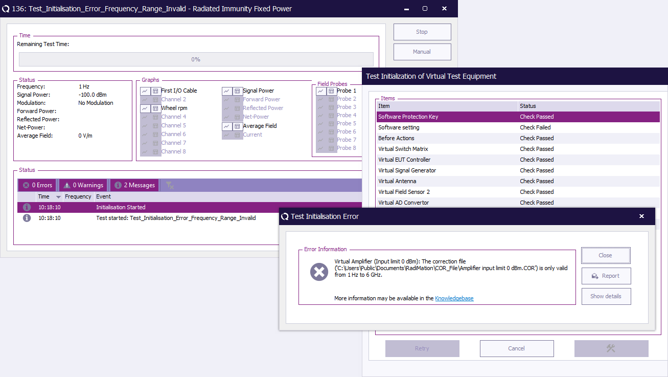
If an error occurs during the system check the user informed about the error and given additional information so the cause of the error can be corrected. | If an error occurs during the system check the user informed about the error and given additional information so the cause of the error can be corrected. | ||
[[Image:Test Initialisation Error Frequency Range Invalid.png]] | |||
==Amplifier protection== | |||
== Amplifier protection == | |||
During EMC tests, there are three different situations where amplifier protection is needed: | During EMC tests, there are three different situations where amplifier protection is needed: | ||
* If an input level above the maximum allowed input level of the amplifier is supplied to the input, the input stage of the amplifier can be damaged. Limiting the output of the signal generator to protect the input of the amplifier will only be correct if the cable losses (which are frequency dependent) between the signal generator and amplifier are taken into account. Otherwise the maximum input to the amplifier will be higher at low frequencies. | |||
* If the amplifier is used above it’s maximum allowed output power for an extensive period of time the amplifier life will be reduced significantly. This is especially through for high power amplifiers with tubes in the final stages. Further more, limiting the maximum output power of the RF amplifier will keep the amplifier in it’s linear region, avoiding non linear distortion and / or a distorted AM signal. Limiting the output power of the amplifier can be realized with a coupler and power meter, connected at the output of the amplifier. To measure the correct output power of the amplifier, the frequency response of cables between the coupler and power meter must be corrected for. | |||
* When a poor antenna match is encountered most of the RF power is reflected back into the amplifier. Most amplifiers do not appreciate this while the reflected power will cause self-heating. | |||
{{RadiMation}} supports three levels of amplifier protection: | |||
* The maximum input level to the amplifier can be limited. To correct for cable losses between the signal generator and the power amplifier, a correction graph can be entered. | |||
* The maximum output power of the amplifier can be limited. To correct for cable losses between the coupler and the power sensor, a correction graph can be entered. | |||
* The maximum reflected power to the amplifier can be limited. To correct for cable losses between the coupler and the power sensor, a correction graph can be entered. | |||
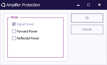
In the case the software wants to drive the amplifier outside it’s predefined settings, the software will limit the generator level, output power or reflected power to the maximum allowed value. | |||
[[Image:Amplifier Protection Configuration Window.png]] | |||
==Manual mode | == Manual mode == | ||
=== Goal === | |||
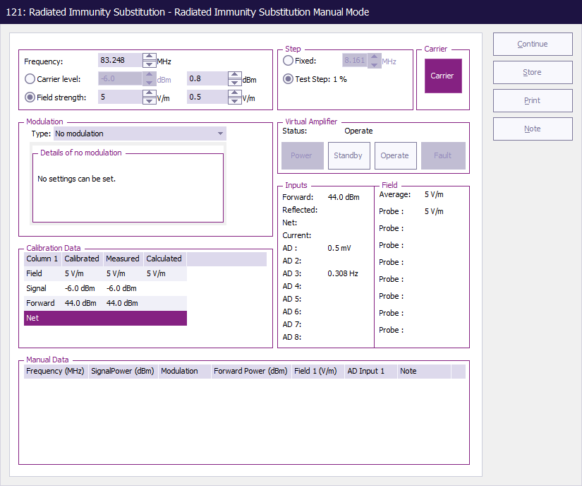
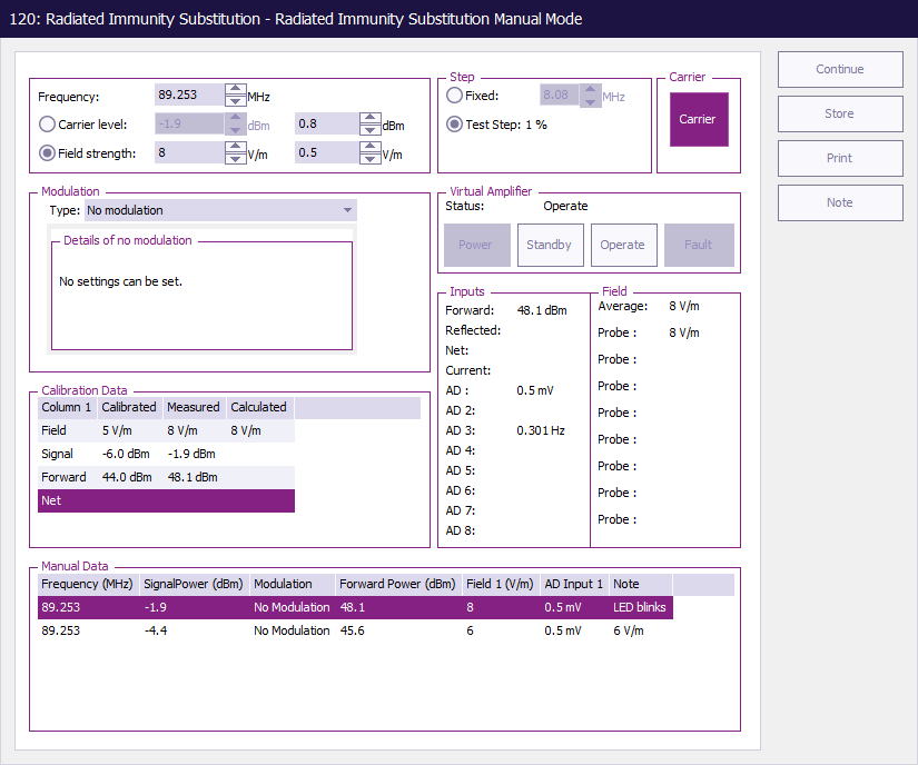
At any moment during a test, the software can be switched to manual mode by simply pressing the “Manual” button. When the manual mode is entered, the software will automatically switch off the output power. The picture below shows the manual mode window. | At any moment during a test, the software can be switched to manual mode by simply pressing the “Manual” button. When the manual mode is entered, the software will automatically switch off the output power. The picture below shows the manual mode window. | ||
[[Image:Radiated Immunity Substitution Manual Mode.png]] | |||
In the “manual mode” window, the immunity system can be completely manual controlled. The RF output can be switched on and off and the frequency and the amplitude can be changed. | In the “manual mode” window, the immunity system can be completely manual controlled. The RF output can be switched on and off and the frequency and the amplitude can be changed. | ||
| Line 359: | Line 462: | ||
Manual mode can be used for one of the following purposes: | Manual mode can be used for one of the following purposes: | ||
#Examine the performance of an EUT in a small frequency band | # Examine the performance of an EUT in a small frequency band | ||
#Change the frequency and/or test level and continue with the automated test at this new frequency and/or test level settings. | # Change the frequency and/or test level and continue with the automated test at this new frequency and/or test level settings. | ||
#Make notes during the test, to record EUT failure (see also “event lists”) | # Make notes during the test, to record EUT failure (see also “event lists”) | ||
#Verify the functionality of the software and or test system | # Verify the functionality of the software and or test system | ||
===Entering Manual Data=== | === Entering Manual Data === | ||
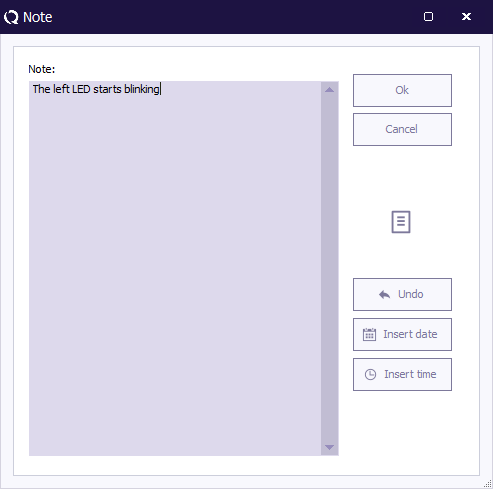
When in manual mode the user can explore the area around the desired frequency point and determine the behavior of the EUT. In case the user wants to store information during a manual mode session the store button should be pushed. A note window appears in which the user can add his observations. | When in manual mode the user can explore the area around the desired frequency point and determine the behavior of the EUT. In case the user wants to store information during a manual mode session the store button should be pushed. A note window appears in which the user can add his observations. | ||
[[Image:Note window.png]] | |||
This note together with all relevant data will be stored and showed in the manual data view. Manual data like all other data collected in {{RadiMation}} is available at all times after the test. | |||
[[Image:Radiated Immunity Substitution Manual Mode with Manual Date.png]] | |||
===Displayed values=== | === Displayed values === | ||
In manual mode, the software will display: | In manual mode, the software will display: | ||
| Line 404: | Line 509: | ||
The software will use the following different calculation methods: | The software will use the following different calculation methods: | ||
==== Signal power test ==== | |||
When a signal power substitution test is performed, the software will use the signal generator level, which is recorded during calibration, to resolve the “calculated field” value. If the gain of the amplifier changes after the calibration file is made, the software will not detect this. For this reason, this method will make an error during the calculation of the field, when the gain of the amplifier is changed. | When a signal power substitution test is performed, the software will use the signal generator level, which is recorded during calibration, to resolve the “calculated field” value. If the gain of the amplifier changes after the calibration file is made, the software will not detect this. For this reason, this method will make an error during the calculation of the field, when the gain of the amplifier is changed. | ||
| Line 414: | Line 519: | ||
Because of this, the software will display a difference between the measured field and the calculated field when the modulation is applied. The calculated field will give the same reading as the field strength indicated in the calibration file, and the measured field strength will indicate the RMS field of the RF signal with the modulation applied. | Because of this, the software will display a difference between the measured field and the calculated field when the modulation is applied. The calculated field will give the same reading as the field strength indicated in the calibration file, and the measured field strength will indicate the RMS field of the RF signal with the modulation applied. | ||
==== Forward power test ==== | |||
When a forward power substitution test is performed, the software will use the forward power level, which is recorded during calibration, to calculate the “calculated field” value. While the forward power is kept constant during this test method, even if the gain of the amplifier changes, the software will calculate the correct value for the “calculated field” | When a forward power substitution test is performed, the software will use the forward power level, which is recorded during calibration, to calculate the “calculated field” value. While the forward power is kept constant during this test method, even if the gain of the amplifier changes, the software will calculate the correct value for the “calculated field” | ||
| Line 429: | Line 534: | ||
Also, slight differences in the calculated field strength can occur due to field sensor and power meter uncertainties. | Also, slight differences in the calculated field strength can occur due to field sensor and power meter uncertainties. | ||
==== Net power test ==== | |||
When a net power (FWD - RFL) substitution test is performed, the software will use the net power level, which is recorded during calibration, to calculate the “calculated field” value. While the net power is kept constant during this test method, even if the gain of the amplifier changes or more energy is reflected back into the amplifier, the software will calculate the correct value for the “calculated field” | When a net power (FWD - RFL) substitution test is performed, the software will use the net power level, which is recorded during calibration, to calculate the “calculated field” value. While the net power is kept constant during this test method, even if the gain of the amplifier changes or more energy is reflected back into the amplifier, the software will calculate the correct value for the “calculated field” | ||
| Line 435: | Line 540: | ||
#The calculated signal generator power is directly copied from the signal generator setting in the manual mode control window. | #The calculated signal generator power is directly copied from the signal generator setting in the manual mode control window. | ||
#The calculated forward power in this situation will be copied from the measured forward power window. | #The calculated forward power in this situation will be copied from the measured forward power window. | ||
#The net power value will be calculated from the measured forward power and reflected power levels. | #The net power value will be calculated from the measured forward power and reflected power levels. | ||
===Calculation of the field during modulation=== | === Calculation of the field during modulation === | ||
During a substitution test according to the net power calibration method, the net power is set to the same value as the net power during calibration. This is always done without modulation. When the modulation is switched on (for example 80% AM, 1000 kHz, without peak conservation), the net power will be lower (due to the modulation). The principal of a substitution test requires no correction for this change in net power. | During a substitution test according to the net power calibration method, the net power is set to the same value as the net power during calibration. This is always done without modulation. When the modulation is switched on (for example 80% AM, 1000 kHz, without peak conservation), the net power will be lower (due to the modulation). The principal of a substitution test requires no correction for this change in net power. | ||
However, this will result in a lower calculated field as well, because | However, this will result in a lower calculated field as well, because {{RadiMation}} uses the net power to calculate the field. | ||
During manual mode (while performing a net power test), changing the test level will change the net power, generated. Because of this, the software will derive the same value for the “calculated” and “measured field” as for the “calibration file” field, making it easier to check the performance of the system. | During manual mode (while performing a net power test), changing the test level will change the net power, generated. Because of this, the software will derive the same value for the “calculated” and “measured field” as for the “calibration file” field, making it easier to check the performance of the system. | ||
| Line 449: | Line 555: | ||
Slight differences in the calculated field strength can occur due to field sensor and power meter uncertainties. | Slight differences in the calculated field strength can occur due to field sensor and power meter uncertainties. | ||
=== Changing the current test level === | |||
When the current test level is changed, the {{RadiMation}} software automatically displays the new calculated field strength (or injected current) for this test level. Furthermore the Forward power, net power, measured Field strength and/or AD channels will be shown on the screen (only if the required field sensor(s), AD channels or power meter(s) are selected under the | |||
When the current test level is changed, the | |||
Configuration, test site pull down menu). | Configuration, test site pull down menu). | ||
| Line 464: | Line 566: | ||
When the shift key is pressed together with the up and down arrows, the level will change with a value of the step size divided by 10. | When the shift key is pressed together with the up and down arrows, the level will change with a value of the step size divided by 10. | ||
===Changing the current test frequency=== | === Changing the current test frequency === | ||
During manual mode the test frequency can be changed. The step size for the frequency changes can be altered with the “step size” button. When the frequency is changed, | During manual mode the test frequency can be changed. The step size for the frequency changes can be altered with the “step size” button. When the frequency is changed, {{RadiMation}} will display the calculated field strength for the new frequency point. | ||
Furthermore the Forward power, Reflected power, Transmitted power and measured field strength will be displayed (only if these devices are selected under the Configuration, test site pull down). | Furthermore the Forward power, Reflected power, Transmitted power and measured field strength will be displayed (only if these devices are selected under the Configuration, test site pull down). | ||
| Line 473: | Line 575: | ||
When the shift key is pressed together with the up and down arrows, the frequency will change with a value of the step size divided by 10. | When the shift key is pressed together with the up and down arrows, the frequency will change with a value of the step size divided by 10. | ||
=== Short cut keys in manual mode === | |||
===Short cut keys in manual mode=== | |||
The following short cut keys can be used during manual mode. | The following short cut keys can be used during manual mode. | ||
{|class="wikitable" | |||
!Key || Function | |||
|- | |||
|Up || Carrier level up. | |||
|- | |||
|Down || Carrier level down. | |||
|- | |||
|Left || Carrier frequency down. | |||
|- | |||
|Right || Carrier frequency up. | |||
|- | |||
|N,n || Set carrier on. | |||
|- | |||
|F,f || Set carrier off. | |||
|} | |||
=== Continuing a test === | |||
Continuing a test at a different test level | Continuing a test at a different test level | ||
When, during manual mode, the test level has been changed, | When, during manual mode, the test level has been changed, {{RadiMation}} will ask you to continue with the new test level or to continue at the old test level. | ||
Continuing a test at a different frequency | Continuing a test at a different frequency. | ||
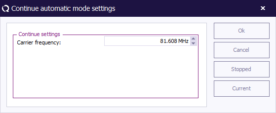
When, during manual mode, the test frequency has been changed, | When, during manual mode, the test frequency has been changed, {{RadiMation}} will ask you to continue with the new start frequency or to continue at the old test frequency. | ||
[[Image:Manual Mode Continue Frequency.png]] | |||
==Tolerance== | |||
== Tolerance == | |||
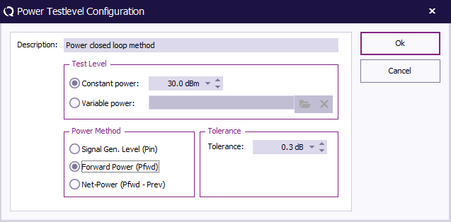
For every radiated immunity test you can define a tolerance. This tolerance has great effect on the measurement. If you choose the tolerance to large then the test results are not usable, if you choose the tolerance to small then it could be that {{Radimation}} has problems performing the test correctly. For example if you define a tolerance of 0.1 dB and your system is only capable of measuring with an uncertainty of 0.2dB than it could be you get a very large event log. So what does it really mean this tolerance? The best way is to explain by using an example. Suppose you are performing a fixed power test, leveling is set on netpower. You have told {{Radimation}} to generate 50 dBm with a tolerance of 0.2 dB. When {{Radimation}} is leveling the power it will accept any power level between 50 and 50.2 dBm as a correct leveled value, and will continue with the test. | |||
== Multiband == | |||
{{:Multiband-radiated-immunity-testlevels}} | |||
[[Category:Manual]] | |||
Latest revision as of 10:50, 11 November 2024
Radiated immunity[edit]
Radiated immunity test are a simulation of R.F. fields generated by strong transmitters as walky-talkies, mobile phones, porto-phones and broadcast transmitters.
During radiated immunity tests, a RF field is generated in the test anechoic chamber. Different EMC standards use different methods to generate this field. The RadiMation® test software supports the following four different methods for radiated immunity tests:
- Substitution method
- Field leveling method
- Fixed generator method
- Performance level method
For more information, please read the chapters 'Substitution test method', 'Fixed Field test method', 'Fixed Power test method' and 'Minimum performance test method', Each test method has it’s own benefits and draw backs.
Substitution test method[edit]
To perform radiated immunity tests according to the substitution' method, the empty anechoic chamber is first calibrated. The calibration file is then used generate the same power into the transmitting antenna as was needed during the calibration, to achieve the desired field strength (with the EUT in the anechoic chamber).
For immunity tests according to IEC 1000-4-3, normally a shielded, full anechoic chamber is used. The chamber must have a minimum of 1.5 m * 1.5 m square homogeneous field area in front of the transmitting antenna.
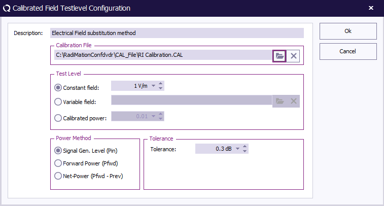
The transmitting antenna should be preferable at a distance of 3 meters from the Equipment Under Test. Before actual tests can take place, calibration of the test set-up is required. See the chapter on Calibration for more information about the method for a 1-point calibration, and the method used for a 16-point field homogeneity check as required by IEC 1000-4-3.
During the calibration, a calibration file is made, which contains the drive power levels for each test frequency. The values recorded in the calibration file are depended on the type of calibration.
Three different types can be used:
- Signal generator level
- Forward power
- Net power (Forward-Reflected)
The calibration files are downwards compatible. This means that a Net power calibration file can be used to perform a Forward power or signal generator level test and a Forward power calibration file can be used to perform a signal generator level test.
The recorded value is the value necessary to generate a constant field in the anechoic chamber. For example, if a test level of 10 V/m has to be generated, the generated field in the anechoic chamber must be 10 V/m (- 0 dB + 6 dB) on 75% of the 16 test points in the 1.5 m * 1.5 m area (See Calibration).
After the test set-up has been calibrated, tests can be performed using the calibration file. Care should be taken for selecting the correct calibration file. The calibration file(s) for horizontal and vertical antenna polarization are quite often different. Chamber characteristics and dimensions cause these differences.
Benefits[edit]
Substitution method tests have a high level of reproducibility. In contradiction to the field leveling method no correction is made for the influence on the field strength caused by the EUT.
| # | Device name | Tab in RadiMation® configuration window |
|---|---|---|
| Signal Generator | Devices 1 | |
| Amplifier | Devices 1 | |
| Coupler | Devices 1 | |
| Forward Power meter | Devices 1 | |
| Reflected Power meter Pref | Devices 1 | |
| Antenna | Devices 1 | |
| Cables | ||
| 1 | Cable SG -> amplifier | Cables |
| 2 | Cable amplifier -> coupler | Cables |
| 3 | Cable coupler -> antenna | Cables |
| 4 | Cable coupler -> refl power meter | Cables |
| 5 | Cable couper -> fwd power meter | Cables |
| Note: | Usage of cable correction factors is not mandatory. However, using correction factors will increase measurement accuracy during immunity measurements.
Although, during immunity measurements according to the substitution method, cable correction factors will increase the accuracy of measured/displayed power values. The generated field accuracy will however be the same when using correction factors or not. When in doubt contact your reseller. |
Configuration window[edit]
The (substitution) configuration window looks as followed:
- Dwell Time: The dwell time is applied after the levelling routine has finished.
- Fixed dwell time: The fixed dwell time is a fixed time period.
- External: The external dwell time can be used with an external EUT controller. RadiMation® asks the EUT controller is the dwell time is finished. The EUT controller is determining if the dwell time has finished.
Fixed Power test method[edit]
Fixed generator tests can be useful during various kinds of EMC tests. During current injection tests, this method can be used to achieve the maximum injected current the amplifier is able to generate. Although this will not be a constant current over the frequency range, it can be useful during engineering work.
Fixed generator tests can be performed in three different ways:
- Fixed signal generator output level. Tests with a fixed generator output level do not take cable losses and amplifier frequency response into account. No power meters are needed during these tests and therefore, the test speed is higher than the fixed forward and fixed transmitted power tests.
- Fixed Forward power level Tests with a fixed forward power level do take cable losses and amplifier frequency response into account. One power meter is required during these tests. This test method does not take VSWR mismatch between the amplifier and current probe into account (i.e.: the forward power and transfer impedance of the current probe alone are not enough to calculate the actually injected current).
- Tests with a fixed transmitted power level take cable losses, amplifier frequency response and VSWR mismatch into account. Two power meters are required during these tests, one to measure the forward power, and one to measure the reflected power. The difference between forward power and reflected power is the transmitted power.
| # | Device name | Tab in RadiMation® configuration window |
|---|---|---|
| Signal Generator | Devices 1 | |
| Amplifier | Devices 1 | |
| Coupler | Devices 1 | |
| Forward Power meter | Devices 1 | |
| Reflected Power meter | Devices 1 | |
| Antenna | Devices 1 | |
| Cables | ||
| 1 | cable sg -> Amplifier | Cables |
| 2 | cable amplifier -> Coupler | Cables |
| 3 | cable coupler -> Antenna | Cables |
| 4 | cable coupler -> fwd power meter | Cables |
| 5 | cable Couper -> refl | Cables |
| Note: | Usage of cable correction factors is not mandatory. However, using correction factors will increase measurement accuracy during immunity measurements.
When in doubt contact your reseller. |
Fixed Field test method[edit]
During Radiated immunity tests according to the “field leveling” method, the generated field during the test is real time leveled to the desired value. For “Field leveling” tests, no calibration files are required. Some EMC standards, like automotive standards, describe field leveling test methods.
| # | Device name | Tab in RadiMation® configuration window |
|---|---|---|
| Signal Generator | Devices 1 | |
| Amplifier | Devices 1 | |
| Coupler | Devices 1 | |
| Forward Power meter | Devices 1 | |
| reflected Power meter | Devices 1 | |
| Antenna | Devices 1 | |
| Field sensor | Field probes | |
| Cables | ||
| 1 | cable sg -> amplifier | Cables |
| 2 | cable amplifier -> coupler | Cables |
| 3 | cable coupler -> antenna | Cables |
| 4 | cable coupler -> fwd power meter | Cables |
| 5 | cable coupler -> refl power meter | Cables |
| Note: | Usage of cable correction factors is not mandatory. However, using correction factors will increase measurement accuracy during immunity measurements.
When in doubt contact your reseller. |
Triplate test method[edit]
The triplate test is a substitution test, based on a triplate calibration. The triplate test is almost the same as the substitution test. The major difference is the amount of points and the determination of the needed power. The triplate impedance is determined during the calibration, using 5 calibrations. To calculate the required power the following formula is used:
Formula 4-1
where
Formula 4-2: Calculation of middle power
To configure a triplate test you need to open the configuration window.
In the configuration window, you need to specify the calibration file you wish to use. Please note that it is possible to select a five-point calibration file as well as a one-point calibration. This is done so that you can verify your one point calibration. Don’t forget to define the following points:
- Testlevel
- Dwelltime
- Antenna distance, in our case the triplate
- Amplifier protection
Press the Start test button to start the test.
| # | Device name | Tab in RadiMation® configuration window |
|---|---|---|
| Signal Generator | Devices 1 | |
| Amplifier | Devices 1 | |
| Coupler | Devices 1 | |
| Forward Power meter | Devices 1 | |
| Reflected Power meter | Devices 1 | |
| Antenna | Devices 1 | |
| Output coupler | Devices 2 | |
| Output power meter | Devices 2 | |
| Cables | ||
| 1 | cable sg -> amplifier | Cables |
| 2 | cable amplifier -> coupler | Cables |
| 3 | cable coupler -> antenna | Cables |
| 4 | cable coupler -> fwd power meter | Cables |
| 5 | cable coupler -> refl power meter | Cables |
| 6 | cable triplate -> coupler | Cables |
| 7 | cable coupler -> output power meter | Cables |
| Note: | Usage of cable correction factors is not mandatory. However, using correction factors will increase measurement accuracy during immunity
measurements. When in doubt contact your reseller. |
Frequency Change Mode test methods[edit]
Most EMC standards do not describe if, or how the RF signal must be switched on and off between the test frequencies.
In real world situations, transitions in RF fields occur quite often. For example, switching on a hand held transmitter or mobile phone would give a transition in the RF field. For this reason, if the used test standard does not prescribe a defined method to handle the field between test points, we recommend to use the “stress tested” method. During this test method, the RF signal is switched on and off between each test point.
RadiMation® supports four different ways to generate the RF signal between test frequencies. These four methods can be used during substitution, current leveling, fixed generator and minimum performance level tests. For more information on these methods, see the paragraphs:
- Stress test method
- Ramp method
- Constant method
- Fast Constant method
Next to these 'standard' test methods RadiMation® supports the so-called minimum performance method described in paragraph 3.4.6.
Stress test method[edit]
During the stress test method, The RF test signal is switched on and off between test points. Transients in the RF field can cause great influence on electronic equipment, where a constant RF field with the same amplitude, does not have any influence. The “stress tested” test method therefore is a worst case test method, which is not required for all EMC standards. However, since this test method simulates the real world situation in the best way, we recommend using this method as the standard method, unless there is a very good reason to test the EUT with another method.
Ramp method[edit]
During the Ramp method, for each test point, the RF signal is ramped up from a level below the required level. The ramp up and ramp down time, as well as the attenuation, is software configurable. After testing for a period of the “Dwell time”, the RF signal is ramped down to a level of below the test level.
|
Constant method[edit]
During the constant method, the RF field is kept constant as good as possible (i.e. the field is not switched off between test point). Of course, any test set-up (signal generator, amplifier, anechoic cabling and injection clamp) will have a frequency response, which is not completely flat. Because of this frequency response, switching between frequency points will always give a slight change in RF level. Depending on the frequency response, the gain of the system for the next frequency point can be greater or smaller than the gain of the previous frequency point. To avoid positive RF level transitions during frequencies changes (which will have over testing as a result) the software determines if the drive level for the next frequency point is higher or lower than the drive level of the current frequency point. If the drive level for the next frequency point is lower, first the amplitude is decreased and then the frequency is incremented. However, if the drive level for the next frequency point is higher, first the frequency is increased and then the amplitude is increased. The dwell time starts after the correct power level has been reached, and modulation when configured is applied.
Fast constant method[edit]
As for the constant method, during the fast constant method, the RF field is kept constant as good as possible (i.e. the field is not switched off between test point). In contradiction to the constant field method, the modulation is not switched on and off during the test. This means that the software measures power and field with the modulation switched on. The software will correct for measurement errors due to the modulation. Although this will result in slightly higher test errors, no transients in the RF field will occur caused by modulation switching. This test method will be faster than constant field-testing caused by the lack of leveling time. Depending on the quality of the test equipment and the frequency step size, the amplitude of the test signal will slightly change. Using a small step size will minimize this problem. Due to the method described above, during the constant field method, over testing does not occur.
| Note: | Powermeter that are not using an RMS detector, should not be used in combination with Fast constant mode |
Minimum performance Method[edit]
The RadiMation® package also supports a specific method to determine the minimum performance level of a Equipment Under Test. This method differentiates itself from the aforementioned methods that is does not generate a fixed specified field strength but a varying field strength based on the susceptibility of the Device Under Test.
The method relies heavily on EUT monitoring (see chapter 8) to determine at which level the Equipment Under Test is influenced. Before the test is started the relevant A/D-channels have to be configured. Pushing the input button on the configuration screen does this.
The test is started at a (low) field strength level after which the field strength is increased with a specified increment till either of both situations arises. The field strength is limited by amplifier protection or the Equipment Under Test will be influenced in such way that the specified limits are exceeded. The field strength is than reduced with a specified step and the software will change to the next frequency point. This test will result in a graph showing the level to which the Equipment Under Test is unaffected by a radiated field.
Calibration methods[edit]
Signal generator level calibration[edit]
During signal generator level calibration only the signal generator level is recorded during the calibration. During a signal generator power substitution test, the signal generator level to input of the amplifier, is kept the same as recorded during the calibration. This method does not take amplifier instability into account. During this calibration method, no power meters are required. This method is less accurate than the FWD power and transmitted power calibrations and therefore not recommended for full compliance tests. During a signal level calibration, the field strength during calibration is recorded.
Forward power calibration[edit]
During a Forward power calibration, the forward power to the transmitting antenna is recorded. During a forward power substitution test, the FWD power to the antenna is kept the same as during the calibration. By this method, amplifier drift will have no influence on the test. When a forward calibration is made, this calibration file can also be used to perform a signal generator substitution test. During a forward power calibration, the signal generator level and the field strength during calibration is recorded.
Net power calibration[edit]
During a net power calibration, the forward and reflected power to the antenna is recorded. The difference between the forward power and reflected power is the net power. During a test, the net power is kept the same as during calibration. When a large metallic, EUT is placed in front of the antenna, some R.F. energy is reflected back into the antenna, resulting in a worse V.S.W.R. When only forward power is calibrated, this effect is not compensated for. When net power is calibrated, the by the antenna transmitted power is kept the same as during calibration. When a net power calibration is made, this calibration file can also be used to perform a signal generator substitution test or a forward power substitution test. During a forward power calibration, the signal generator level, forward power level and the field strength during calibration is recorded.
Modulation[edit]
Amplitude Modulation (AM)[edit]
During most radiated and conducted immunity tests, the test signal must be Amplitude Modulated (AM). If a modulation is chosen, this modulation will only be switched on during the period of the dwell time. In between test points, when the test signal is set and adjusted to the next frequency point, the modulation is switched off. The reason for this is that measurements of the field or current, with the modulation switched on, are less accurate than without modulation. This is essentially important during real time leveled tests. Dependent on the capabilities of the signal generator used, internal and external modulation sources can be used.
For most EMC standards the RF signal is modulated with a 1 kHz, 80% AM modulation.
No conservation[edit]
When 'None' conservation is selected, the AM will be applied on top of the CW signal, and the maximum value of the modulated signal will be higher than the not moduldated CW signal.
According to EN61000-4-3 and EN61000-4-6, the amplitude of the modulated RF signal is 1,8 times the amplitude of the not modulated CW RF signal. When 'None conservation' is selected, the peak value of the AM signal equals ((100% + Modulation depth) / 100%) times the peak value of the not modulated CW signal.
Voltage conservation[edit]
For automotive standards, as for the 95/54/EEC, the peak value of the modulated signal should be regulated in such a way that the peak voltage value of the modulated signal equals the peak voltage value of the not modulated CW signal.
RadiMation® supports this type of AM modulation with the option 'Voltage conservation' (also known as 'Amplitude conservation'). The amplitude of the AM modulated signal is adjusted in such a way that the peak voltage value of the modulated signal equals the peak voltage value of the not modulated CW signal.
Power conservation[edit]
When 'Power conservation' is selected, the amplitude of the AM modulated signal is adjusted in such a way that the RMS power contents of the modulated signal equals the RMS power contents of the not modulated CW signal.
Displaying of modulated values[edit]
In RadiMation®, the measured field, measured voltages and measured currents are always displayed as corresponding non-modulated test-levels. The measured values are corrected for the applied modulation and the possible applied modulation conservation.
The reason for the displaying of corrected measurement data is caused by the specification of test levels in the standards. Every standard is specifying the testlevel in the unmodulated CW-values. When also modulation should be applied, this is separately specified in the standard. A more specific requirement for voltage or power conservation of the modulation can also be specified. If modulation and possibly conservation is applied, this will result in a different measurement value which will be displayed in the graph. In that situation the graphs will show a higher or lower test-level compared to the test-level specification from the standard. When the measured values are corrected for the applied modulation and the possible applied conservation, the displayed values in the graphs will be corresponding CW values, which will be directly comparable to the test-level specifications from the standard. The displaying of the corrected measurement values will thus prevent a lot of confusion between the measurement values and the test-level specification in the standards.
An example: in a radiated immunity substitution test with no modulation with a test-level of 10 V/m, the measured field strength will be 10 V/m, and this value will also be displayed. If the same test is performed with 80% AM Modulation, a field strength of 18 V/m will be measured. In this case the software will however display 10 V/m, because that is the requested test-level. The displayed values are still measured values, but the measured values are corrected for the applied modulation. The graphs are also corrected to show the relevant level if conservation of the modulation is used. So if during the above example also voltage conservation of the modulation is selected, the carrier level will be 5.1 dB lower. The measured field strength will be 10 V/m again, and the graph will also display 10 V/m. As a result of this implementation, in an optimal situation, the values of calculated field, measured field and specified test-level should be displayed at the same values in the graphs.
Also the graphs for the current, voltage and power levels are corrected for the applied modulation and conservation. The corrections on the measured values are depending on the ability of the used measuring device to correctly measure a value when modulation is applied. If for example a field strength sensor makes an error during the measurement of the electrical field when modulation is also applied, the corrected and displayed value of the measured field strength will also not be accurate. This situation only applies to situations where a modulated signal is measured, and that is only possible when the 'fast constant' frequency change mode is used during a single band test or the 'Apply modulation outside dwell-time' is enabled during a multiband test.
Frequency modulation (FM)[edit]
Frequency modulation is a simulation of the frequency modulated signals. During frequency modulation the carrier frequency is slightly changed to another frequency to encode information in the transmitted signal. This is for example used by FM radio broadcasts, where the carrier frequency is slightly modified in the frequency according to the audio that should be transmitted. A larger variation in the carrier frequency then encodes a louder value, and the speed in which the carrier is fluctuating denotes the frequency of the generated tone. A 1 kHz tone that is transmitted by a FM radio broadcast station at 90.8 MHz thus varies the carrier frequency between 90.725 MHz and 90.875 MHz at a rate of 1 kHz.
There are 2 parameters that define how the frequency modulation should be performed:
- Frequency: The frequency that specifies the rate at which the carrier frequency should be changed.
- Frequency deviation: The maximum change in the carrier frequency that should be applied. The carrier frequency is thus variated between the (tested frequency - frequency deviation) and (tested frequency + frequency deviation).
When frequency modulation is used during EMC testing, the frequency variation of the carrier frequency is applied as a sine wave over time, where the specified deviation is the maximum frequency shift of the carrier frequency which is being applied in the top of the sine wave. The frequency in which the frequency deviation sine wave is applied, is the specified frequency modulation frequency.
In the earlier given example of the FM radio broadcast station, the settings of the FM modulation would thus be: frequency: 1 kHz, frequency deviation: 75 kHz.
Pulse modulation (PM)[edit]
Pulse modulation is a simulation of the digital modulation technique which is for example used by mobile phones. With pulse modulation the CW carrier is temporarily enabled (on) and disabled (off). While the carrier is disabled, no signal is being generated during that off-time period. There are few parameters that define how the pulse modulation should be performed:
- Frequency: The frequency that determines how often the pulses are being generated.
- Duty cycle: The relation (in percentage) between the on-time compared to the combined on and off-time. The duty cycle should always be between 0 % and 100 %
- Pulse width: The duration of the on-time of a single generated pulse. The pulse width should always be smaller than: 1 / Frequency [Hz].
Different standards describe different parameters for the pulse modulation that should be applied. The picture below shows an example pulse modulation with a 50% duty cycle.
There is a relation between the parameters of the pulse modulation, and modifying one parameter will automatically change one of the other parameters.
Gated/Burst pulse modulation (BPM)[edit]
Gated pulse modulation uses the same modulation settings as the above described pulse modulation. These settings are also applied similiar.
Gated pulse modulation is applied on top of the above described pulse modulation, by doing so it adds the following functionality:
Only a set amount of "pulses" will be generated after which the remainder of the "gating period" is waited before the next cycle is started.
To implement this gated pulse modulation uses the following additional parameters:
- Pulse count [-]: The amount of pulses that must be gated in each burst.
- Gating period [s]: The duration of time between the start moments of each generated burst cycle.
Software checks:[edit]
To prevent accidental use of wrong calibration files and / or equipment, RadiMation® checks if calibration file has been made with the same equipment and under the same conditions as the currently configured test. The following items are checked, each time a test is started:
- Check for the correct antenna polarization
- Check for the correct amplifier
- Check for the correct signal generator
- Check for the correct power meter
- Check for the correct current sensor
- Check for the correct distance between EUT and antenna
- Check if the selected test start frequency is higher then the lowest calibration frequency
- Check if the selected test stop frequency is lower then the highest calibration frequency
- Power delivery test
The power delivery test is is done to ensure that the amplifier and powermeters are connected, and it can also be used to determine if the antenna is connected (based on the reflected power). The power delivery test is done in the middle of the frequency band of the current test. The signal generator is set to the ‘Signal generator starting level’, and then a step of +4 dB is done. If the powermeter reading also increases with +4 dB, we do a step of -3 dB. If the powermeter reading also measures a step of -3 dB, we are sure that the amplifiers and powermeters are connected, and the amplifier is in a more or less linear range. If the powermeter reading is not following with the expected step, we just do another +4 dB increment, until the powermeter reading is also increasing with +4 dB. The signal generator level on which the power delivery test is successful is also logged in the eventlog of the test.
If an error occurs during the system check the user informed about the error and given additional information so the cause of the error can be corrected.
Amplifier protection[edit]
During EMC tests, there are three different situations where amplifier protection is needed:
- If an input level above the maximum allowed input level of the amplifier is supplied to the input, the input stage of the amplifier can be damaged. Limiting the output of the signal generator to protect the input of the amplifier will only be correct if the cable losses (which are frequency dependent) between the signal generator and amplifier are taken into account. Otherwise the maximum input to the amplifier will be higher at low frequencies.
- If the amplifier is used above it’s maximum allowed output power for an extensive period of time the amplifier life will be reduced significantly. This is especially through for high power amplifiers with tubes in the final stages. Further more, limiting the maximum output power of the RF amplifier will keep the amplifier in it’s linear region, avoiding non linear distortion and / or a distorted AM signal. Limiting the output power of the amplifier can be realized with a coupler and power meter, connected at the output of the amplifier. To measure the correct output power of the amplifier, the frequency response of cables between the coupler and power meter must be corrected for.
- When a poor antenna match is encountered most of the RF power is reflected back into the amplifier. Most amplifiers do not appreciate this while the reflected power will cause self-heating.
RadiMation® supports three levels of amplifier protection:
- The maximum input level to the amplifier can be limited. To correct for cable losses between the signal generator and the power amplifier, a correction graph can be entered.
- The maximum output power of the amplifier can be limited. To correct for cable losses between the coupler and the power sensor, a correction graph can be entered.
- The maximum reflected power to the amplifier can be limited. To correct for cable losses between the coupler and the power sensor, a correction graph can be entered.
In the case the software wants to drive the amplifier outside it’s predefined settings, the software will limit the generator level, output power or reflected power to the maximum allowed value.
Manual mode[edit]
Goal[edit]
At any moment during a test, the software can be switched to manual mode by simply pressing the “Manual” button. When the manual mode is entered, the software will automatically switch off the output power. The picture below shows the manual mode window.
In the “manual mode” window, the immunity system can be completely manual controlled. The RF output can be switched on and off and the frequency and the amplitude can be changed.
Manual mode can be used for one of the following purposes:
- Examine the performance of an EUT in a small frequency band
- Change the frequency and/or test level and continue with the automated test at this new frequency and/or test level settings.
- Make notes during the test, to record EUT failure (see also “event lists”)
- Verify the functionality of the software and or test system
Entering Manual Data[edit]
When in manual mode the user can explore the area around the desired frequency point and determine the behavior of the EUT. In case the user wants to store information during a manual mode session the store button should be pushed. A note window appears in which the user can add his observations.
This note together with all relevant data will be stored and showed in the manual data view. Manual data like all other data collected in RadiMation® is available at all times after the test.
Displayed values[edit]
In manual mode, the software will display:
Measured values:
- The (maximal 8) field strength(s) [or current] sensors
- The (maximal 8) A/D channels
- Forward power
- Reflected power
- The current sensor value
Calculated value’s:
- Field strength (or current).
- Net power
- Average field value of the selected field sensors
Calibration file information
- The field strength which was used during the generation of the calibration file
- Signal generator power which was required during the generation of the calibration file (during net power, forward and signal power calibrations)
- Forward power which was required during the generation of the calibration file (only during forward and net power calibrations)
- Net power, which was required during the generation of the calibration file (only during net power calibrations). With this information, the functionality of the software and test set-up can be easily verified. Furthermore, this information can be very useful during investigation of the EUT.
Calculation methods
The calculated values are calculated depending on the calibration type (signal power, forward power or net power), selected in the main test window.
The software will use the following different calculation methods:
Signal power test[edit]
When a signal power substitution test is performed, the software will use the signal generator level, which is recorded during calibration, to resolve the “calculated field” value. If the gain of the amplifier changes after the calibration file is made, the software will not detect this. For this reason, this method will make an error during the calculation of the field, when the gain of the amplifier is changed.
Calculation of the field during modulation:
During a substitution test according to the signal power calibration method, the signal generator power is set to the same value as the signal generator power during calibration. This is always done without modulation. When the modulation is switched on (for example 80% AM, 1000 kHz, without peak conservation), the forward power at the output of the amplifier, will be lower (due to the modulation). The software will derive the “calculated field” from the signal generator power and therefore will not correct for this change in output power. The calculated field can not be derived from the forward power because a power meter is not required during signal generator power calibrations and tests.
Because of this, the software will display a difference between the measured field and the calculated field when the modulation is applied. The calculated field will give the same reading as the field strength indicated in the calibration file, and the measured field strength will indicate the RMS field of the RF signal with the modulation applied.
Forward power test[edit]
When a forward power substitution test is performed, the software will use the forward power level, which is recorded during calibration, to calculate the “calculated field” value. While the forward power is kept constant during this test method, even if the gain of the amplifier changes, the software will calculate the correct value for the “calculated field”
The net power value can not be calculated with a forward power calibration file, and will therefore not be displayed.
Calculation of the field during modulation:
During a substitution test according to the forward power calibration method, the forward power is set to the same value as the forward power during calibration. This is always done without modulation. When the modulation is switched on (for example 80% AM, 1000 kHz, without peak conservation), the forward power will be lower (due to the modulation). The principal of a substitution test requires no correction for this change in forward power.
During manual mode, (while performing a forward power test), changing the test level will change the forward power, generated. Because of this, the software will derive the same value for the “calculated’ and “measured field” as for the “calibration file” field, making it more easy to check the performance of the system.
Due to a high-reflected power level, the calculated field can be inaccurate. This will be especially true if the reflected power is less than 20 dB lower than the forward power. Also, slight differences in the calculated field strength can occur due to field sensor and power meter uncertainties.
Net power test[edit]
When a net power (FWD - RFL) substitution test is performed, the software will use the net power level, which is recorded during calibration, to calculate the “calculated field” value. While the net power is kept constant during this test method, even if the gain of the amplifier changes or more energy is reflected back into the amplifier, the software will calculate the correct value for the “calculated field”
- The calculated signal generator power is directly copied from the signal generator setting in the manual mode control window.
- The calculated forward power in this situation will be copied from the measured forward power window.
- The net power value will be calculated from the measured forward power and reflected power levels.
Calculation of the field during modulation[edit]
During a substitution test according to the net power calibration method, the net power is set to the same value as the net power during calibration. This is always done without modulation. When the modulation is switched on (for example 80% AM, 1000 kHz, without peak conservation), the net power will be lower (due to the modulation). The principal of a substitution test requires no correction for this change in net power.
However, this will result in a lower calculated field as well, because RadiMation® uses the net power to calculate the field.
During manual mode (while performing a net power test), changing the test level will change the net power, generated. Because of this, the software will derive the same value for the “calculated” and “measured field” as for the “calibration file” field, making it easier to check the performance of the system.
In this situation in contradiction to the forward power method, errors in the calculated power, due to a high-reflected power level will not occur.
Slight differences in the calculated field strength can occur due to field sensor and power meter uncertainties.
Changing the current test level[edit]
When the current test level is changed, the RadiMation® software automatically displays the new calculated field strength (or injected current) for this test level. Furthermore the Forward power, net power, measured Field strength and/or AD channels will be shown on the screen (only if the required field sensor(s), AD channels or power meter(s) are selected under the Configuration, test site pull down menu).
In manual mode, depending on the test method (signal generator calibration, forward power calibration or net power calibration) respectively, the signal generator level, forward power or net power will be changed.
The test level can be changed with the mouse button (using the up and down arrows), be typed in using the keyboard or be changed using the up and down arrows on the keyboard. For all methods, the step size of the increments is determined by the “step size” value behind the “test level” field.
When the shift key is pressed together with the up and down arrows, the level will change with a value of the step size divided by 10.
Changing the current test frequency[edit]
During manual mode the test frequency can be changed. The step size for the frequency changes can be altered with the “step size” button. When the frequency is changed, RadiMation® will display the calculated field strength for the new frequency point. Furthermore the Forward power, Reflected power, Transmitted power and measured field strength will be displayed (only if these devices are selected under the Configuration, test site pull down).
The test frequency can be changed with the mouse button (using the up and down arrows), be typed in using the keyboard or be changed using the up and down arrows on the keyboard. For all methods, the step size of the increments is determined by the “step size” value behind the “frequency” field.
When the shift key is pressed together with the up and down arrows, the frequency will change with a value of the step size divided by 10.
Short cut keys in manual mode[edit]
The following short cut keys can be used during manual mode.
| Key | Function |
|---|---|
| Up | Carrier level up. |
| Down | Carrier level down. |
| Left | Carrier frequency down. |
| Right | Carrier frequency up. |
| N,n | Set carrier on. |
| F,f | Set carrier off. |
Continuing a test[edit]
Continuing a test at a different test level
When, during manual mode, the test level has been changed, RadiMation® will ask you to continue with the new test level or to continue at the old test level.
Continuing a test at a different frequency.
When, during manual mode, the test frequency has been changed, RadiMation® will ask you to continue with the new start frequency or to continue at the old test frequency.
Tolerance[edit]
For every radiated immunity test you can define a tolerance. This tolerance has great effect on the measurement. If you choose the tolerance to large then the test results are not usable, if you choose the tolerance to small then it could be that RadiMation® has problems performing the test correctly. For example if you define a tolerance of 0.1 dB and your system is only capable of measuring with an uncertainty of 0.2dB than it could be you get a very large event log. So what does it really mean this tolerance? The best way is to explain by using an example. Suppose you are performing a fixed power test, leveling is set on netpower. You have told RadiMation® to generate 50 dBm with a tolerance of 0.2 dB. When RadiMation® is leveling the power it will accept any power level between 50 and 50.2 dBm as a correct leveled value, and will continue with the test.
Multiband[edit]
Test levels[edit]
In RadiMation’s MultiBand testing modules, "test levels" are settings that control how power is regulated, limited, and measured during EMC testing. They play a crucial role in ensuring that devices under test are exposed to consistent and precise levels across multiple frequency bands. Here’s how test levels work and how they affect your testing process in RadiMation:
Types of Test Levels[edit]
In RadiMation’s MultiBand modules, there are different types of test levels that each serve a unique purpose during testing:
- Power Leveling (Test Level): This type of test level sets the target power level that the test equipment should aim to achieve. It ensures that a specific level of electromagnetic energy is consistently applied to the device under test.
- Power Limitation (Limit Level): This is used to cap the maximum power level that the system can apply. By setting limit levels, you ensure that the power applied never exceeds safe or specified levels, helping to protect the device under test from overexposure.
- Measurement Inputs (Input Level): Input levels define what measurements are necessary during the test. For instance, they can specify particular signals or parameters that the system should measure at specific points during the test, allowing you to monitor the test environment and the device's behavior closely.
How Test Levels Are Applied[edit]
Test levels in RadiMation can be configured to suit the specifics of your testing requirements. Each test level can have its own configuration, and the RadiMation software allows you to select and adjust these levels within the test module’s interface. For example, you can set different test levels for different frequency bands, helping to simulate various conditions that the device might encounter.
When setting up a test in a MultiBand module, you’ll be able to choose a test level from RadiMation’s built-in list of available test levels for a given module. Once a test level is selected, the system will:
- Regulate Power: If you selected a power leveling type, the system will continuously adjust to maintain the specified power level during the test.
- Enforce Limits: If you set a limit level, RadiMation will prevent the power from exceeding this limit, which can be especially useful when testing devices with sensitive components.
- Measure Inputs: For input levels, the system will capture and log the specified measurement data. This data will come available in the test data and can be used for furthet visualization and reporting.
RadiMation’s MultiBand modules also allow you to set up multiple test levels for a single test. This flexibility enables you to create complex testing scenarios. Test levels in RadiMation’s MultiBand modules are essential settings for regulating, limiting, and measuring the levels too which the devices under test are submitted. By configuring these levels appropriately, you can ensure accurate and effective testing outcomes.
Available test levels[edit]
Test level: Power closed loop method[edit]
| A field to enter a description for the power test level method being configured. |
| A test level option where the power is kept constant at a specified level, in this case, -100.0 dBm. |
| An option to set a range or variable power level for testing. This option is disabled in the image. |
| A power method that uses the signal generator level (Pin) as the reference for power measurement. |
| A power method that uses the forward power (Pfwd) as the reference for power measurement. |
| A power method that calculates net power by subtracting the previous power level (Prev) from the forward power (Pfwd). |
| A field to set a tolerance level for power measurement in dB, which defines the acceptable variation range. |
Test level: Electrical field substitution method[edit]
| A field to enter a description for the calibrated field test level method being configured. |
| A field to specify the calibration file path, which defines calibration settings for the test level. |
| A test level option where the field strength is kept constant at a specified level, in this case, 1 V/m. |
| An option to set a range or variable field strength for testing. This option is disabled in the image. |
| An option to set a calibrated power level for testing, currently disabled. |
| A power method that uses the signal generator level (Pin) as the reference for field strength measurement. |
| A power method that uses the forward power (Pfwd) as the reference for field strength measurement. |
| A power method that calculates net power by subtracting the previous power level (Prev) from the forward power (Pfwd). |
| A field to set a tolerance level for field strength measurement in dB, which defines the acceptable variation range. In this case, it is set to 0.3 dB. |
Test level: Electrical field closed loop method[edit]
| A field to enter a description for the field test level method being configured. |
| A dropdown menu to select the device used to measure the field, in this case, a Field Probe. |
| A test level option where the field strength is kept constant at a specified level, in this case, 1 V/m. |
| An option to set a range or variable field strength for testing. This option is disabled in the image. |
| A field to set a tolerance level for field strength measurement in dB, which defines the acceptable variation range. In this case, it is set to 0.3 dB. |
| A section to select from multiple probes (Probe 1 to Probe 8) for field measurement. Probe 1 and Probe 2 are selected in this image. |
Test level: Magnetic field substitution method[edit]
| A field to enter a description for the calibrated magnetic field test level method being configured. |
| A field to specify the calibration file path, which defines calibration settings for the magnetic field test level. |
| A test level option where the magnetic field strength is kept constant at a specified level, in this case, 120.0 dBpT. |
| An option to set a range or variable magnetic field strength for testing. This option is disabled in the image. |
| A leveling method that uses the signal generator level (Pin) as the reference for magnetic field strength measurement. |
| A leveling method that uses the forward power (Pfwd) as the reference for magnetic field strength measurement. |
| A leveling method that calculates net power by subtracting the previous power level (Prev) from the forward power (Pfwd). |
| A leveling method that utilizes a multimeter and resistor to measure magnetic field strength. |
| A leveling method that uses a powermeter and current sensor to measure magnetic field strength. |
| A leveling method that uses an oscilloscope and resistor for magnetic field strength measurement. |
| A field to set a tolerance level for magnetic field measurement in dB, defining the acceptable variation range. In this case, it is set to 0.3 dB. |
Test level: Magnetic field closed loop method[edit]
| A field to enter a description for the magnetic field test level method being configured. |
| A dropdown menu to select the device used to measure the magnetic field, in this case, a Multimeter and Resistor. |
| A test level option where the magnetic field strength is kept constant at a specified level, in this case, 120.0 dBpT. |
| An option to set a range or variable magnetic field strength for testing. This option is disabled in the image. |
| A field to set a tolerance level for magnetic field measurement in dB, defining the acceptable variation range. In this case, it is set to 0.3 dB. |
Test level: Calculated electrical field method[edit]
| A field to enter a description for the calculated electrical field method being configured. |
| A section to define the field configuration settings specific to the calculated electrical field method. This may include parameters such as the target field strength or other field-specific configurations. |
| A configuration option to select the power method used in the test. In this case, it is set to "Forward Power" by default, using the forward power as the reference for the electrical field calculation. |
| A field to set the tolerance level for the test, specifying the acceptable variation range for the electrical field measurement. The default value is set to 0.3 dB. |
Available Limits[edit]
Limit: Measured power limit[edit]
| A field to enter a description for the power test level method being configured. |
| A test level option where the power is kept constant at a specified level, in this case, -100.0 dBm. |
| An option to set a range or variable power level for testing. This option is disabled in the image. |
| A power method that uses the signal generator level (Pin) as the reference for power measurement. |
| A power method that uses the forward power (Pfwd) as the reference for power measurement. |
| A power method that calculates net power by subtracting the previous power level (Prev) from the forward power (Pfwd). |
| A field to set a tolerance level for power measurement in dB, which defines the acceptable variation range. |
Limit: Electrical field limit[edit]
| A field to enter a description for the field test level method being configured. |
| A dropdown menu to select the device used to measure the field, in this case, a Field Probe. |
| A test level option where the field strength is kept constant at a specified level, in this case, 1 V/m. |
| An option to set a range or variable field strength for testing. This option is disabled in the image. |
| A field to set a tolerance level for field strength measurement in dB, which defines the acceptable variation range. In this case, it is set to 0.3 dB. |
| A section to select from multiple probes (Probe 1 to Probe 8) for field measurement. Probe 1 and Probe 2 are selected in this image. |
Limit: Calculated electrical field calibration limit[edit]
| A field to enter a description for the calibrated field test level method being configured. |
| A field to specify the calibration file path, which defines calibration settings for the test level. |
| A test level option where the field strength is kept constant at a specified level, in this case, 1 V/m. |
| An option to set a range or variable field strength for testing. This option is disabled in the image. |
| An option to set a calibrated power level for testing, currently disabled. |
| A power method that uses the signal generator level (Pin) as the reference for field strength measurement. |
| A power method that uses the forward power (Pfwd) as the reference for field strength measurement. |
| A power method that calculates net power by subtracting the previous power level (Prev) from the forward power (Pfwd). |
| A field to set a tolerance level for field strength measurement in dB, which defines the acceptable variation range. In this case, it is set to 0.3 dB. |
Limit: Measured current limit[edit]
| A field to enter a description for the current closed loop test level method being configured. |
| A test level option where the current is kept constant at a specified level, in this case, 50 mA. |
| An option to set a range or variable current level for testing. This option is disabled in the image. |
| A field to set a tolerance level for current measurement in dB, defining the acceptable variation range. In this case, it is set to 0.3 dB. |
Limit: Measured voltage limit[edit]
| A field to enter a description for the voltage closed loop test level method being configured. |
| A dropdown menu to select the device used to measure the voltage, in this case, an Oscilloscope. |
| A test level option where the voltage is kept constant at a specified level, in this case, 1 µV. |
| An option to set a range or variable voltage level for testing. This option is disabled in the image. |
| A field to set a tolerance level for voltage measurement in dB, defining the acceptable variation range. In this case, it is set to 0.3 dB. |
Limit: Magnetic field limit[edit]
| A field to enter a description for the magnetic field test level method being configured. |
| A dropdown menu to select the device used to measure the magnetic field, in this case, a Multimeter and Resistor. |
| A test level option where the magnetic field strength is kept constant at a specified level, in this case, 120.0 dBpT. |
| An option to set a range or variable magnetic field strength for testing. This option is disabled in the image. |
| A field to set a tolerance level for magnetic field measurement in dB, defining the acceptable variation range. In this case, it is set to 0.3 dB. |
Limit: Calculated magnetic field limit[edit]
| A field to enter a description for the calibrated magnetic field test level method being configured. |
| A field to specify the calibration file path, which defines calibration settings for the magnetic field test level. |
| A test level option where the magnetic field strength is kept constant at a specified level, in this case, 120.0 dBpT. |
| An option to set a range or variable magnetic field strength for testing. This option is disabled in the image. |
| A leveling method that uses the signal generator level (Pin) as the reference for magnetic field strength measurement. |
| A leveling method that uses the forward power (Pfwd) as the reference for magnetic field strength measurement. |
| A leveling method that calculates net power by subtracting the previous power level (Prev) from the forward power (Pfwd). |
| A leveling method that utilizes a multimeter and resistor to measure magnetic field strength. |
| A leveling method that uses a powermeter and current sensor to measure magnetic field strength. |
| A leveling method that uses an oscilloscope and resistor for magnetic field strength measurement. |
| A field to set a tolerance level for magnetic field measurement in dB, defining the acceptable variation range. In this case, it is set to 0.3 dB. |
Limit: Minimum performance limit[edit]
| A field to enter a description for the minimum performance test level being configured. |
| A field to set the stepdown value, which specifies the amount by which the test level will decrease in each step. The default value is set to 0.2 dB. |
Limit: Calculated electrical field limit[edit]
| A field to enter a description for the calculated electrical field method being configured. |
| A section to define the field configuration settings specific to the calculated electrical field method. This may include parameters such as the target field strength or other field-specific configurations. |
| A configuration option to select the power method used in the test. In this case, it is set to "Forward Power" by default, using the forward power as the reference for the electrical field calculation. |
| A field to set the tolerance level for the test, specifying the acceptable variation range for the electrical field measurement. The default value is set to 0.3 dB. |
Available Inputs[edit]
Input: Power[edit]
| A field to enter a description for the power test level method being configured. |
| A test level option where the power is kept constant at a specified level, in this case, -100.0 dBm. |
| An option to set a range or variable power level for testing. This option is disabled in the image. |
| A power method that uses the signal generator level (Pin) as the reference for power measurement. |
| A power method that uses the forward power (Pfwd) as the reference for power measurement. |
| A power method that calculates net power by subtracting the previous power level (Prev) from the forward power (Pfwd). |
| A field to set a tolerance level for power measurement in dB, which defines the acceptable variation range. |
Input: Electrical field probe[edit]
| A field to enter a description for the field test level method being configured. |
| A dropdown menu to select the device used to measure the field, in this case, a Field Probe. |
| A test level option where the field strength is kept constant at a specified level, in this case, 1 V/m. |
| An option to set a range or variable field strength for testing. This option is disabled in the image. |
| A field to set a tolerance level for field strength measurement in dB, which defines the acceptable variation range. In this case, it is set to 0.3 dB. |
| A section to select from multiple probes (Probe 1 to Probe 8) for field measurement. Probe 1 and Probe 2 are selected in this image. |
Input: Calculated electrical field calibration[edit]
| A field to enter a description for the calibrated field test level method being configured. |
| A field to specify the calibration file path, which defines calibration settings for the test level. |
| A test level option where the field strength is kept constant at a specified level, in this case, 1 V/m. |
| An option to set a range or variable field strength for testing. This option is disabled in the image. |
| An option to set a calibrated power level for testing, currently disabled. |
| A power method that uses the signal generator level (Pin) as the reference for field strength measurement. |
| A power method that uses the forward power (Pfwd) as the reference for field strength measurement. |
| A power method that calculates net power by subtracting the previous power level (Prev) from the forward power (Pfwd). |
| A field to set a tolerance level for field strength measurement in dB, which defines the acceptable variation range. In this case, it is set to 0.3 dB. |
Input: Current sensor[edit]
| A field to enter a description for the current closed loop test level method being configured. |
| A test level option where the current is kept constant at a specified level, in this case, 50 mA. |
| An option to set a range or variable current level for testing. This option is disabled in the image. |
| A field to set a tolerance level for current measurement in dB, defining the acceptable variation range. In this case, it is set to 0.3 dB. |
Input: Calculated current[edit]
| A field to enter a description for the calibrated current substitution method being configured. |
| A field to specify the calibration file path, which defines calibration settings for the current test level. |
| Section to configure the current test level for the test. |
| A test level option where the current is kept constant at a specified level, e.g., 50 mA. |
| An option to set a range or variable current level for testing, allowing dynamic adjustments during the test. |
| An option to set a calibrated power level for testing, which might be disabled if not applicable in the specific test configuration. |
| A power method that uses the signal generator level (Pin) as the reference for current measurement. |
| A power method that uses the forward power (Pfwd) as the reference for current measurement. |
| A power method that calculates net power by subtracting the previous power level (Prev) from the forward power (Pfwd). |
| A field to set a tolerance level for current measurement in dB, defining the acceptable variation range for the current test. For example, it could be set to 0.3 dB. |
Input: Voltage measurement[edit]
| A field to enter a description for the voltage closed loop test level method being configured. |
| A dropdown menu to select the device used to measure the voltage, in this case, an Oscilloscope. |
| A test level option where the voltage is kept constant at a specified level, in this case, 1 µV. |
| An option to set a range or variable voltage level for testing. This option is disabled in the image. |
| A field to set a tolerance level for voltage measurement in dB, defining the acceptable variation range. In this case, it is set to 0.3 dB. |
Input: Calculated voltage[edit]
| A field to enter a description for the calibrated voltage substitution method being configured. |
| A field to specify the calibration file path, which defines calibration settings for the voltage test level. |
| A test level option where the voltage is kept constant at a specified level, in this case, 1 µV. |
| An option to set a range or variable voltage level for testing. This option is disabled in the image. |
| An option to set a calibrated power level for testing, currently disabled. |
| A power method that uses the signal generator level (Pin) as the reference for voltage measurement. |
| A power method that uses the forward power (Pfwd) as the reference for voltage measurement. |
| A power method that calculates net power by subtracting the previous power level (Prev) from the forward power (Pfwd). |
| A field to set a tolerance level for voltage measurement in dB, defining the acceptable variation range. In this case, it is set to 0.3 dB. |
Input Test level: VSWR[edit]
-
 Description The description of the input.
-
Calculation[edit]
The VSWR (Voltage Standing Wave Ratio) test level in RadiMation is a measurement that indicates how well the energy from a signal source is being transferred to a device under test. It provides insight into the efficiency of power delivery, with a lower VSWR indicating better efficiency and minimal energy reflection. This is important in electromagnetic immunity testing to ensure accurate power application across test frequencies.
In RadiMation, the VSWR is calculated based on the Return Loss (RL) between the forward power and reflected power.
- Calculate Return Loss (RL):
In RadiMation, this is calculated as the difference between the forward power and the reflected power.
- Calculate the Reflection Coefficient:
The reflection coefficient is a value derived from the Return Loss. It quantifies the proportion of energy reflected from the device.
- Calculate VSWR:
If the reflection coefficient is 1 (meaning full reflection with no power transfer), the VSWR is set to a high value (e.g., 1000) to represent an infinite VSWR. VSWR measures the standing wave pattern created by the interference between the forward and reflected waves. It’s calculated based on the reflection coefficient as follows:
Input: Magnetic field[edit]
| A field to enter a description for the magnetic field test level method being configured. |
| A dropdown menu to select the device used to measure the magnetic field, in this case, a Multimeter and Resistor. |
| A test level option where the magnetic field strength is kept constant at a specified level, in this case, 120.0 dBpT. |
| An option to set a range or variable magnetic field strength for testing. This option is disabled in the image. |
| A field to set a tolerance level for magnetic field measurement in dB, defining the acceptable variation range. In this case, it is set to 0.3 dB. |
Input: Calculated magnetic field[edit]
| A field to enter a description for the calibrated magnetic field test level method being configured. |
| A field to specify the calibration file path, which defines calibration settings for the magnetic field test level. |
| A test level option where the magnetic field strength is kept constant at a specified level, in this case, 120.0 dBpT. |
| An option to set a range or variable magnetic field strength for testing. This option is disabled in the image. |
| A leveling method that uses the signal generator level (Pin) as the reference for magnetic field strength measurement. |
| A leveling method that uses the forward power (Pfwd) as the reference for magnetic field strength measurement. |
| A leveling method that calculates net power by subtracting the previous power level (Prev) from the forward power (Pfwd). |
| A leveling method that utilizes a multimeter and resistor to measure magnetic field strength. |
| A leveling method that uses a powermeter and current sensor to measure magnetic field strength. |
| A leveling method that uses an oscilloscope and resistor for magnetic field strength measurement. |
| A field to set a tolerance level for magnetic field measurement in dB, defining the acceptable variation range. In this case, it is set to 0.3 dB. |
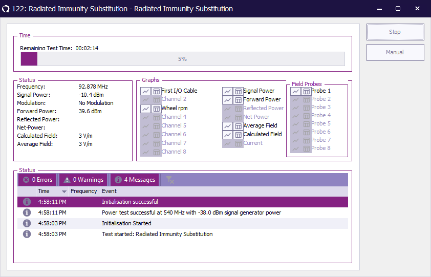

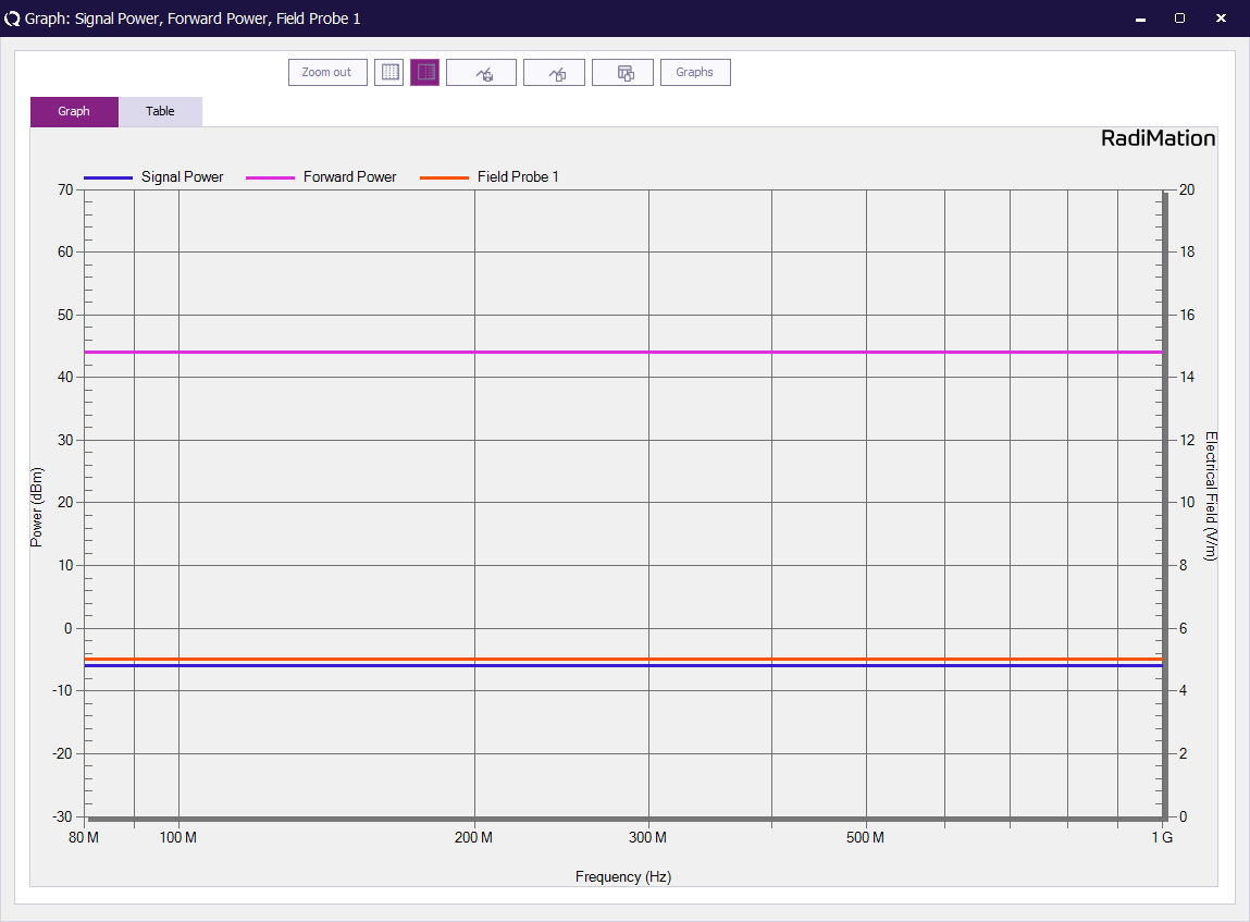
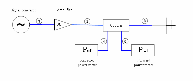
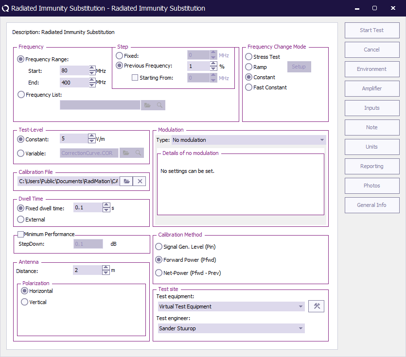

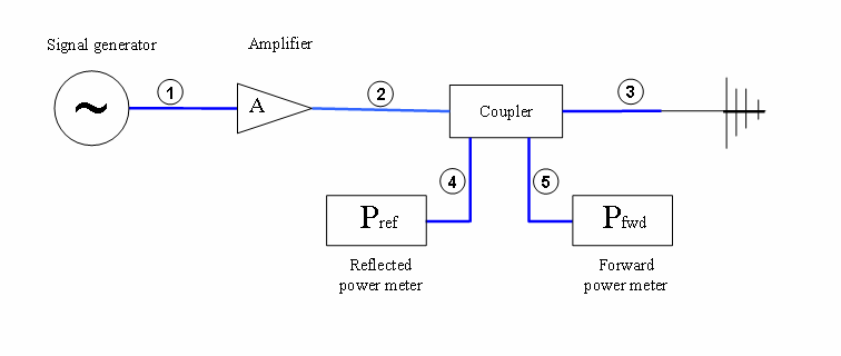

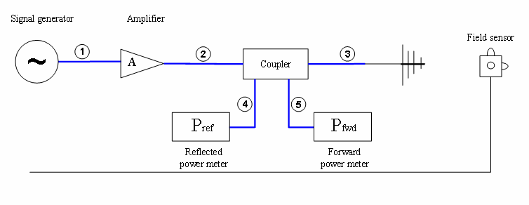
![{\displaystyle P_{mid}(f)[W]={\frac {E_{v}(f)^{2}*h^{2}}{Z(f)}}}](https://wikimedia.org/api/rest_v1/media/math/render/svg/e0aaed03a969f453e05d61eac9d0963d9b09faa1)
![{\displaystyle P_{mid}(f)[W]={\frac {P_{net}[W]+P_{out}[W]}{2}}}](https://wikimedia.org/api/rest_v1/media/math/render/svg/08229641086173a3bfd12f7a682e9f028f89d2e4)

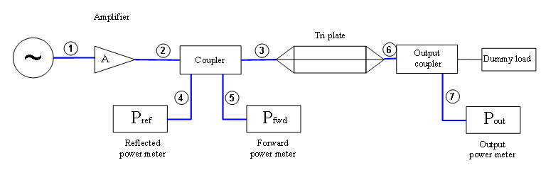
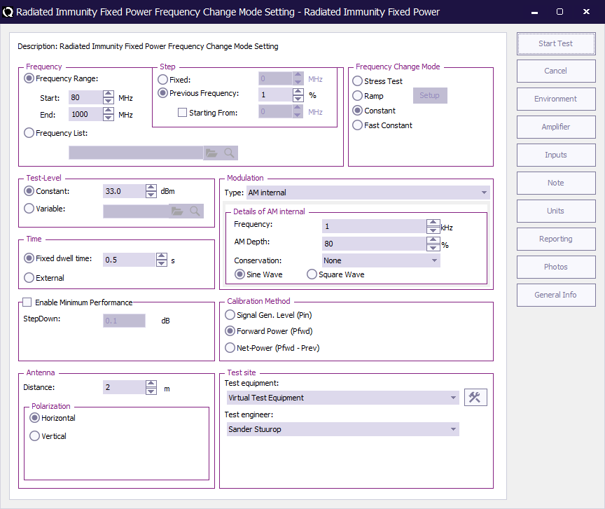
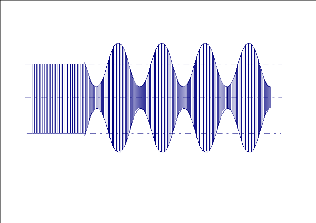
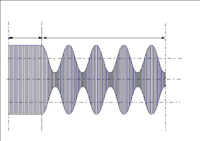
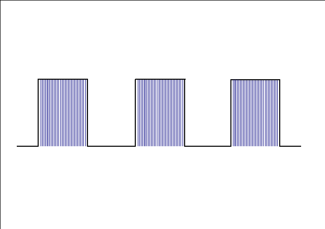
![{\displaystyle pulsewidth[s]={\frac {dutycycle[\%]/100}{frequency[Hz]}}}](https://wikimedia.org/api/rest_v1/media/math/render/svg/82ec9cb84606178458e7effed706ee59ffe0ee89)
![{\displaystyle dutycycle[\%]={\frac {pulsewidth[s]}{frequency[Hz]}}*100}](https://wikimedia.org/api/rest_v1/media/math/render/svg/6e08bdfa5cbd72c36173789c24e8ad050b92bee5)
