Pulsed immunity[edit]
Introduction[edit]
The pulsed immunity test modules are used to record test data in the RadiMation® software. Most of the pulsed immunity tests are carried out manually while the test engineer enters the test results. The report generator can use the results of the tests.
The following pulsed immunity tests are implemented:
- Electro static discharge (ESD) testing
- Electrical Fast Transient (EFT) testing
- Surge testing
ESD testing[edit]
Starting an ESD test[edit]
Loading a TSF file[edit]
To start an ESD test, an EUT file must be defined first. From the EUT file, select
-
 Tests
Tests
- Pulsed immunity
- ESD
A list of Technical Setup Files (TSF files) will be displayed. The test engineer can select one of these TSF files to load all parameters from a previously defined emission test or press cancel to define a new emission test.
After the TSF file has been selected, the emission configuration window will appear.
When a TSF file is loaded, all test parameters will be already configured and pressing the start button on the right side of the screen can start the test.
When a new TSF file is loaded (by pressing New in the TSF selection window) all parameters will be at zero and can be configured by the operator.
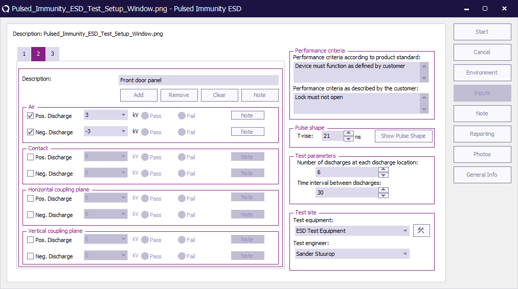
The picture below shows the ESD configuration screen. The operator has to select test levels and pulse polarity. Furthermore the burst waveform has to be configured by the operator. The measurement results can be recorded in the right side of the screen. For each injection mode, the operator can select pass or fail and make notes in the “notes” field.
All configurations (except for the test results) can be stored in a TSF file.
EFT testing[edit]
Single band[edit]
Starting an EFT test[edit]
Loading a TSF file[edit]
To start an EFT test, an EUT file must be defined first. From the EUT file, select
- Tests
- Pulsed immunity
- EFT Multiband
A list of Technical Setup Files (TSF files) will be displayed. The test engineer can select one of these TSF files to load all parameters from a previously defined emission test or press cancel to define a new emission test.
After the TSF file has been selected, the emission configuration window will appear.
When a TSF file is loaded, all test parameters will be already configured and pressing the start button on the right side of the screen can start the test.
When a new TSF file is loaded (by pressing New in the TSF selection window) all parameters will be at zero and can be configured by the operator.
The picture below shows the EFT configuration screen.
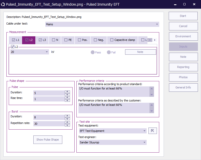
The operator has to select the cable to be tested (AC / DC / IO). The cable under test is part of the EUT so it needs to be configured in the EUT window under cables. Furthermore the burst waveform has to be configured by the operator. The measurement results can be recorded in the right side of the screen. For each injection mode, the operator can select pass or fail and make notes in the “notes” field.
All configurations (except for the test results) can be stored in a TSF file.
 Cable under test Cable under test
|
Selection of cable on which the test is performed. The cable is created in the cable section in the EUT window.
|
| Measurement
|
Configuration of the tests that need to be performed on the specific cable.
| Level
|
The level applied to the cable.
|
| Note
|
A note that can be added before performing the test relate.
|
|
| Pulse shape
|
These parameters describe the characteristics of the applied pulses.
| Pulse Duration
|
The duration of the pulse applied to the cable.
|
| Pulse Rise time
|
The rise time of the pulse applied to the cable.
|
| Burst Duration
|
The duration of the burst applied to the cable.
|
| Burst Repetition rate
|
The repetition rate of the burst applied to the cable.
|
| Show Pulse Shape
|
Display a graphical view of the pulse shape.
|
|
| Performance criteria
|
| Performance criteria according to the product standard
|
In this field the performance criteria according to the standard can be written down.
|
| Performance criteria as described by the customer
|
In this field the performance criteria as described by the customer can be written down.
|
|
| Test site
|
| Test equipment
|
In the test site window the test engineer can select which equipment list will be used during this test.
|
| Test engineer
|
In the test engineer window, the test engineer can select their own name. The test engineer name will be stored by the test results.
|
| Equipment icon
|
By clicking on the equipment icon, the equipment list can be viewed and edited.
|
|
Multi band[edit]
Starting an EFT test[edit]
Loading a TSF file[edit]
To start an EFT test, an EUT file must be defined first. From the EUT file, select
- Tests
- Pulsed immunity
- EFT Multiband
A list of Technical Setup Files (TSF files) will be displayed. The test engineer can select one of these TSF files to load all parameters from a previously defined emission test or press cancel to define a new emission test.
After the TSF file has been selected, the emission configuration window will appear.
When a TSF file is loaded, all test parameters will be already configured and pressing the start button on the right side of the screen can start the test.
When a new TSF file is loaded (by pressing New in the TSF selection window) all parameters will be at zero and can be configured by the operator.
The picture below shows the EFT Multiband configuration screen.
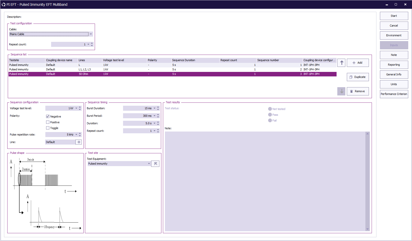
The operator has to select the cable to be tested (AC / DC / IO).
The cable under test is part of the EUT and therefore must be configured in the EUT window under cables.
Within this window, the operator defines the test levels, timing, and coupling line configuration for each EFT sequence.
Measurement results can be entered on the right side of the screen, where each test step can be marked as Pass or Fail.
All configurations (except for the test results) can be stored in a TSF file for later use.
| Cable under test
|
Selection of the cable on which the EFT test is performed. The cable is defined in the EUT configuration under Cables.
|
| Repeat count
|
Defines how many times the complete EFT test configuration is executed.
|
| Sequence list
|
Overview of all EFT test sequences to be performed.
|
| Voltage test level
|
Specifies the burst voltage level to be applied.
|
| Polarity
|
Defines whether the burst polarity is positive, negative, or toggling.
|
| Coupling device configuration
|
Shows the selected coupling device setup.
|
| Line
|
Shows the selected coupling device.
|
| Add / Duplicate / Remove
|
Buttons to create, copy, or delete EFT sequences from the list.
|
| Sequence configuration
|
Defines the test parameters for the currently selected EFT sequence.
|
| Voltage test level
|
Sets the test voltage level for the EFT burst.
|
| Polarity
|
Determines if the pulses are positive, negative, or alternating.
|
| Pulse repetition rate
|
Sets the frequency of the pulses within the burst.
|
| Line
|
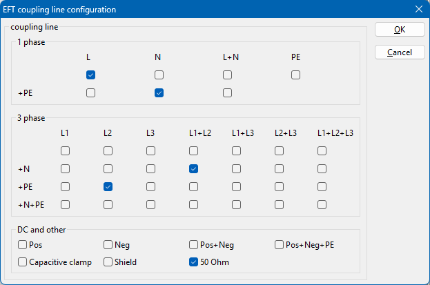
Shows the selected coupling device and is used to opens the Coupling Line Configuration dialog where the operator defines which coupling lines are used for the EFT test.
The coupling line Configuration dialog allows the selection of the coupling line configuration for the device driver found in the testsite.
The operator can select one or more combinations, depending on the test standard requirements.
If no coupling path is selected the pre-existing configuration will not be overwritten.
The coupling line configuration dialog does not remember the previous selected line selection.
Each selected line is tested sequentially; RadiMation automatically creates individual EFT injections for each configuration.
Selecting multiple lines ensures all required coupling paths are tested without manual re-configuration between runs.
If no line is selected when starting the test, RadiMation prompts the user to select at least one coupling path before the test can start.
When multiple coupling paths are selected, RadiMation automatically performs a separate test for each selection in sequence.
The order in which testing on the coupling lines is performed is undefined.
|

|
Note:
|
The coupling configuration dialogue is added in RadiMation 2025.2.1, in older RadiMation releases a single tested coupling line is selected from a predefined list.
|
| Sequence timing
|
Defines timing values used for the EFT bursts.
|
| Burst Duration
|
The duration of a single burst of pulses.
|
| Burst Period
|
The interval between two bursts.
|
| Duration
|
Total time that the sequence runs.
|
| Repeat count
|
Number of times the sequence is repeated.
|
| Pulse shape
|
Displays a visual representation of the EFT pulse and burst waveform.
|
| Test Equipment
|
Displays the selected test generator or system used for the EFT test.
|
| Test results
|
Shows the test status (Not tested, Pass, or Fail) and allows the operator to add notes related to the test.
|
Surge testing[edit]
Single band[edit]
Starting an Surge test[edit]
Loading a TSF file[edit]
To start a Surge test, an EUT file must be defined first. From the EUT file, select
- Tests
- Pulsed immunity
- Surge Multiband
A list of Technical Setup Files (TSF files) will be displayed. The test engineer can select one of these TSF files to load all parameters from a previously defined emission test or press cancel to define a new emission test.
After the TSF file has been selected, the emission configuration window will appear.
When a TSF file is loaded, all test parameters will be already configured and pressing the start button on the right side of the screen will start the test.
When a new TSF file is loaded (by pressing New in the TSF selection window) all parameters will be at zero and can be configured by the operator.
The picture below shows the Surge configuration screen.
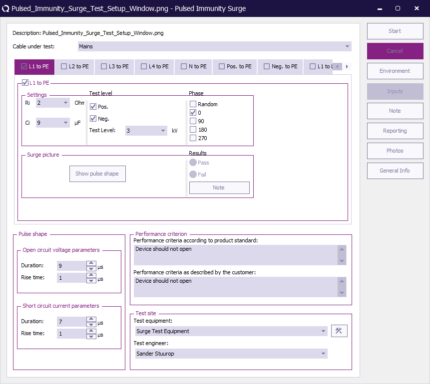
The operator has to select cable to be tested (1 or 3 phase / DC / IO). The cable under test is part of the EUT so it needs to be configured in the EUT window under cables. Furthermore the operator has to configure the test level, polarity, phase and the internal resistor and capacitor of the generator. The measurement results can be recorded in the right side of the screen. For each injection mode, the operator can select pass or fail and make notes in the “notes” field.
All configurations (except for the test results) can be stored in a TSF file.
| Cable under test
|
Selection of cable on which the test is performed. The cable is created in the cable section in the EUT window.
|
| Pulse shape
|
| Open circuit duration
|
The duration of the open circuit applied to the cable.
|
| Open circuit rise time
|
The rise time of the open circuit applied to the cable.
|
| Short circuit duration
|
The duration of the short circuit applied to the cable.
|
| Short circuit rise time
|
The rise time of the short circuit applied to the cable.
|
|
| Performance criteria window
|
| Performance criteria according to the product standard
|
In the Performance criteria according to the product standard window the performance criteria according to the standard can be written down.
|
| Performance criteria as described by the customer
|
In the Performance criteria as described by the customer window the performance criteria as described by the customer can be written down.
|
|
| Test site
|
| Test equipment
|
In the test site window the test engineer can select which equipment list will be used during this test.
|
| Test engineer
|
In the test engineer window, the test engineer can select their own name. The test engineer name will be stored by the test results.
|
| Equipment icon
|
By clicking on the equipment icon, the equipment list can be viewed and edited.
|
|
Multi band[edit]
Starting an Surge test[edit]
Loading a TSF file[edit]
To start a Surge test, an EUT file must be defined first. From the EUT file, select
- Tests
- Pulsed immunity
- Surge Multiband
A list of Technical Setup Files (TSF files) will be displayed. The test engineer can select one of these TSF files to load all parameters from a previously defined emission test or press cancel to define a new emission test.
After the TSF file has been selected, the emission configuration window will appear.
When a TSF file is loaded, all test parameters will be already configured and pressing the start button on the right side of the screen will start the test.
When a new TSF file is loaded (by pressing New in the TSF selection window) all parameters will be at zero and can be configured by the operator.
The picture below shows the Surge Multiband configuration screen.
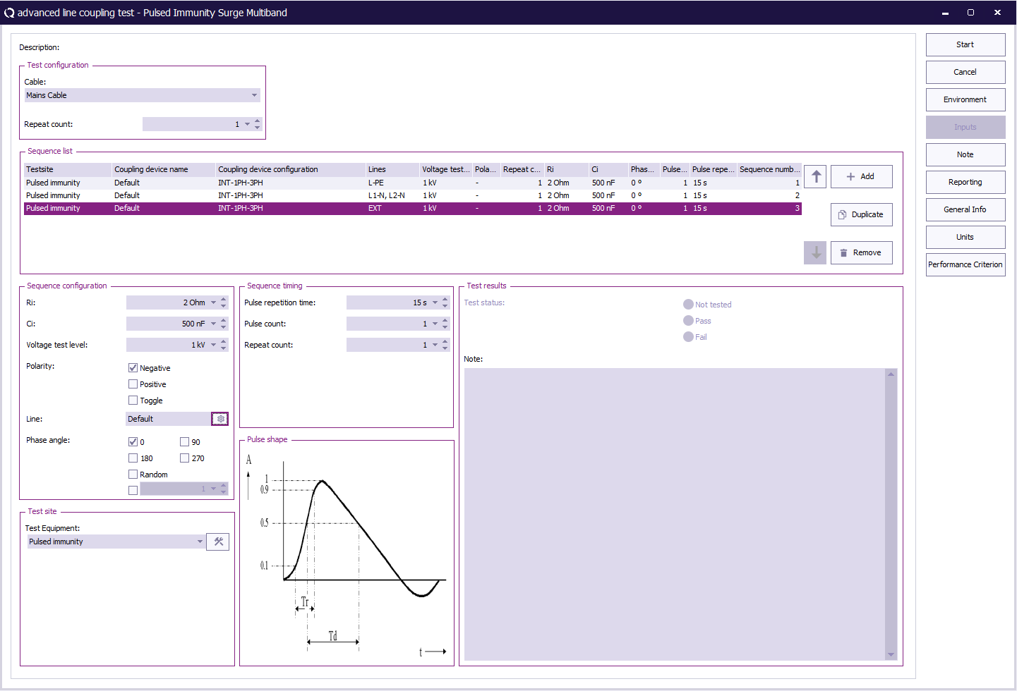
The operator must select the cable to be tested (AC / DC / IO), which is part of the EUT configuration under cables.
The window allows configuration of voltage level, polarity, coupling network, and phase angles.
Measurement results can be recorded on the right side of the screen. For each injection mode, the operator can select Pass or Fail and add remarks in the notes field.
All configurations (except for test results) can be saved in a TSF file.
| Cable under test
|
Selection of the cable on which the Surge test is performed. The cable is created in the EUT window under Cables.
|
| Repeat count
|
Defines how many times the complete Surge test configuration is executed.
|
| Sequence list
|
Overview of all Surge test sequences to be executed.
|
| Voltage test level
|
Specifies the voltage amplitude for the surge pulse.
|
| Polarity
|
Defines whether the surge polarity is positive, negative, or toggling.
|
| Ri / Ci
|
Defines the internal resistance and capacitance values of the coupling network.
|
| Phase angle
|
Specifies the mains phase angle(s) at which the surge is applied (0°, 90°, 180°, 270°, or Random).
|
| Coupling device configuration
|
Shows the coupling device setup (e.g. internal or external).
|
| Line
|
Shows the selected coupling device.
|
| Add / Duplicate / Remove
|
Buttons to add, copy, or delete sequences from the list.
|
| Sequence configuration
|
Defines the Surge test settings for the selected sequence.
|
| Ri
|
Internal resistance of the coupling network.
|
| Ci
|
Internal capacitance of the coupling network.
|
| Voltage test level
|
Sets the surge voltage amplitude.
|
| Polarity
|
Selects the polarity of the surge pulse.
|
| Phase angle
|
Defines the phase(s) of the mains voltage at which the surge is triggered.
|
| Line
|
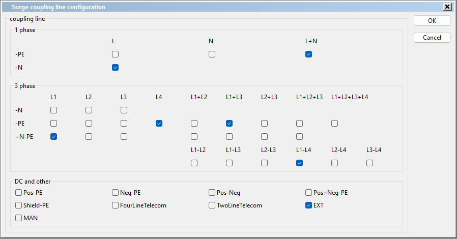
Shows the selected coupling device and is used to opens the Coupling Line Configuration dialog where the operator defines which coupling lines are used for the Surge test.
The coupling line Configuration dialog allows the selection of the coupling line configuration for the device driver found in the testsite.
The operator can select one or more combinations, depending on the test standard requirements.
If no coupling path is selected the pre-existing configuration will not be overwritten.
The coupling line configuration dialog does not remember the previous selected line selection.
Each selected line is tested sequentially; RadiMation automatically creates individual EFT injections for each configuration.
Selecting multiple lines ensures all required coupling paths are tested without manual re-configuration between runs.
If no line is selected when starting the test, RadiMation prompts the user to select at least one coupling path before the test can start.
When multiple coupling paths are selected, RadiMation automatically performs a separate test for each selection in sequence.
The order in which testing on the coupling lines is performed is undefined.
|
|
|
Note:
|
The coupling configuration dialogue is added in RadiMation 2025.2.1, in older RadiMation releases a single tested coupling line is selected from a predefined list.
|
| Sequence timing
|
Defines timing values for surge generation.
|
| Pulse repetition time
|
Time interval between two consecutive surges.
|
| Pulse count
|
Number of surges per test sequence.
|
| Repeat count
|
Number of times the sequence is repeated.
|
| Pulse shape
|
Displays a graphical representation of the 1.2/50 µs surge waveform showing rise and decay times.
|
| Test Equipment
|
Shows the selected test system for the Surge test. The configuration button opens the equipment setup dialog.
|
| Test results
|
Displays the test status (Not tested, Pass, or Fail) and provides a note field for operator comments or observations.
|


