How to perform a MIL-STD-461 RE103, radiated emissions, antenna spurious and harmonic outputs test.[edit]
This application note explains how the MIL-STD-461 RE103, radiated emissions, antenna spurious and harmonic outputs test can be performed with RadiMation®.
The "RE103, radiated emissions, antenna spurious and harmonic outputs" test applies as an alternative to CE106 for testing transmitters with their intended antennas, ensuring emissions do not exceed RE102 limits in transmit mode. It is preferred for systems with active antennas or non-standard impedance curves. It applies from 10 kHz to 40 GHz, excluding the signal bandwidth and ±5% of the fundamental frequency, with larger exclusions for high-power Navy shipboard systems.
The exact requirements and test methods for the RE103 are specified in the MIL-STD-461.
Necessary equipment[edit]
The following devices should be configured:
- Measurement receiver
- Band rejection network
- Attenuators / filters
- Antenna
EUT Testing[edit]
EUT Testing equipment

The configuration of the eut testing test site should contain the following devices:
| # |
Device name |
Tab in test site configuration window |
note
|
|
Antenna |
Devices 1 |
The receiving antenna to use
|
|
Spectrum analyser |
Devices 2 |
The measurement receiver or spectrum analyser to use
|
| Cables
|
| ① |
Cable preamp-> analyser |
Cables |
Cable with a correction file specified for the band rejection filter or high pass filter
|
| ② |
Cable preamp-> analyser |
Cables |
Cable with the specified loss of the used attenuator
|
| ③ |
Cable preamp-> analyser |
Cables |
Cable with a correction file specified for cable loss
|
Configure the EUT test[edit]
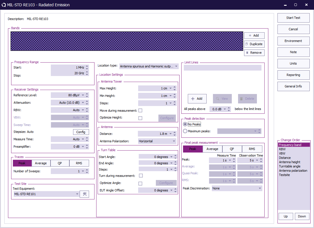
To perform the eut test, create a radiated emissions multiband test.
The radiated emission multiband test, can be started by selecting from the menu:
-
 Tests
Tests
-
 Radiated Emission
-
 Multiband

 Start Start
|
The start frequency of the test. For example 1 MHz.
|
 Stop Stop
|
The stop frequency of the test. For example 20 MHz.
|
 Reference Level Reference Level
|
The reference level set in the analyser. This setting is not used when a receiver is used.
|
 Attenuation Attenuation
|
The attenuation set in the receiver.
|
 RBW RBW
|
The RBW set in the receiver.
|
 Step size Step size
|
The step size set in the receiver.
|
 Measure time Measure time
|
The measure time set in the receiver.
|
 Preamplifier Preamplifier
|
The preamplifier setting set in the receiver.
|
 Traces Traces
|
The type of trace set in the receiver. For MIL-STD-461 RE103 the peak detector is used.
|
 Test Equipment Test Equipment
|
The equipment used for the measurement.
|
 Location type Location type
|
The type of measurement that should be used. Set this to Antenna spurious and harmonic outputs.
|
 Max Height Max Height
|
The maximum height for the antenna tower.
|
 Min Height Min Height
|
The minimal height for the antenna tower.
|
 Steps Steps
|
The number of height positions to measure.
|
 Move during measurement Move during measurement
|
If the antenna tower can move during the measurement.
|
 Optimize Height Optimize Height
|
Find the optimal emission around a certain height. This is normally not used during MIL-STD-461 RE103 measurements, and can thus be unchecked.
|
 Distance Distance
|
The distance between the antenna and the EUT. The antenna distance determined in 5.19.3.4a.
|
 Antenna Polarization Antenna Polarization
|
Which polarization is used, Vertical, Horizontal or Both.
|
 Start Angle Start Angle
|
The minimal turn table angle.
|
 End Angle End Angle
|
The maximum turn table angle.
|
 Steps Steps
|
The number of angles to measure.
|
 Turn during measurement Turn during measurement
|
If the turn table can move during the measurement. This is normally not used during MIL-STD-461 RE103 measurements, and can thus be unchecked.
|
 Optimize Angle Optimize Angle
|
Find the optimal emission around a certain angle. This is normally not used during MIL-STD-461 RE103 measurements, and can thus be unchecked.
|
 EUT Angle Offset EUT Angle Offset
|
The offset of the EUT on the table. This is normally not used during MIL-STD-461 RE103 measurements, and can thus be set to 0 degrees.
|
 Limit Lines Limit Lines
|
The applicable limit line can be added, in this example the "MIL-STD-461 RE102 XXX-XXX" limit line file.
|
 All peaks above x dB below the limit line All peaks above x dB below the limit line
|
Which level above x dB below the limit line the peaks should be detected.
|
 Peak detection Peak detection
|
How many peaks should be detected automatically. For a MIL-STD-461 RE103 peaks will be selected manually
|
 Final peak measurement Final peak measurement
|
It is possible to perform a final measurement on a peak with the selected detectors. Normally no final measurement is needed for the MIL-STD-461 RE103 measurement, and all detectors can thus be unselected.
|
 Tests
Tests
 Radiated Emission
 Multiband
