Chapter 5
Conducted immunity[edit]
Introduction[edit]
Conducted immunity tests are a simulation of R.F. currents in cables, induced by R.F. fields of transmitters working in the lower frequency bands. At frequencies below 30 MHz it is quite difficult to generate an R.F. field in an anechoic chamber. This is caused by the fact that the wavelength of the test signal becomes increasingly longer at lower frequencies (l [m]= 300 / f [MHz]) and therefore, the transmitting antenna becomes either very long (± 5 meter at 30 MHz) or very in-efficient.
The dimensions of most anechoic chambers do not allow antennas greater than 5 meter (labda / 2). On the other hand, when smaller antennas are used, the power needed to generate a field becomes very high. At 30 MHz with a 3 meter EUT, Antenna separation, a transmitted power of approximately 500 W is needed. For frequencies below 30 MHz the desired power rapidly increases to several Kilowatts. During conducted immunity tests, a RF current is injected in to the cabling of the equipment under test. Different EMC standards use different methods to control the injected current.
The RadiMation® test software supports four different methods for current injection.
Substitution method[edit]
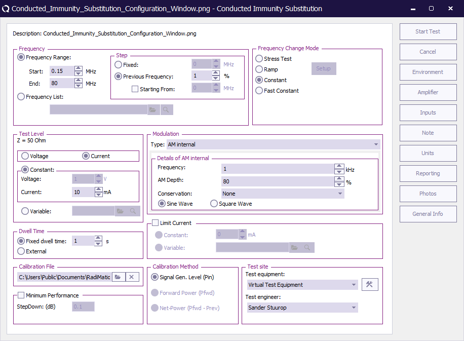
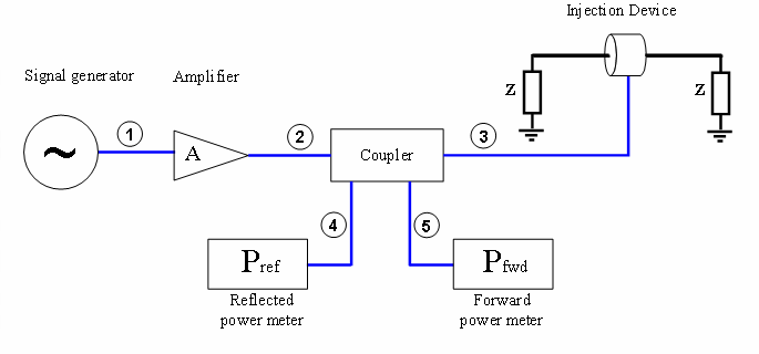
During current injection tests according to the substitution method, a constant voltage is applied to the injection clamp.
-
 Tests
Tests
-
 Conducted Immunity
-
 Substitution
-
-
-
Related standards are:
EN 61000-4-6[edit]
For tests in accordance to EN 61000-4-6 a CDN (Coupling Device Network) or injection clamp with characteristic impedance of 150 Ω is used. Before actual tests can take place, calibration of the test set-up is required. See the “Calibration” chapter for the method to calibrate the current clamp. During the calibration, a calibration file is made, which contains the drive levels for each test frequency. The values recorded in the calibration file are the forward power levels to the clamp, necessary to inject a constant current into a 150 Ω reference wire. For example, if a test level of 10 Vrms has to be injected, a current of 33 mA is injected in the 150 Ω reference wire (10 Vrms / (150 Ω + 150 Ω)).
After the test set-up has been calibrated, tests can be performed using the calibration file.
The current injected into the cabling of the EUT (Equipment Under Test) during a test, will be determined by the impedance of the cable and the 150 Ω of the injection clamp. Worst case, the injected current will be twice as high as the injected current during the calibration.
95/54/EEG[edit]
Tests for automotive and military applications often are revered to as Bulk Current Injection (B.C.I.) tests. For tests in accordance to 95/54/EEG a Bulk Current Injection clamp is used. Before actual tests can take place, calibration of the test set-up is required.
Chapter 12 describes the method for the calibration of the bulk current injection set-up. During the calibration, a calibration file is made, which contains the drive levels for each test frequency. The values recorded in the calibration file are the forward power levels to the clamp, necessary to inject a constant current into a 100 Ω calibration Jig.
After the test set-up has been calibrated, tests can be performed using the calibration file.
| Device name | Tab in RadiMation® configuration window |
|---|---|
| Signal Generator | Standard 1 |
| Amplifier | Standard 1 |
| Coupler | Standard 1 |
| Power meter Pfwd | Standard 1 |
| Power meter Refl | Standard 1 |
| Injection device | Standard 2 |
| # | Device name | Tab in RadiMation® configuration window |
|---|---|---|
| 1 | Cable SG-> Amplifier | Cables |
| 2 | Cable Amplifier-> coupler | Cables |
| 3 | Cable Coupler-> Antenna | Cables |
| 4 | Cable Coupler-> fwd Power meter | Cables |
| 5 | Cable Coupler-> refl power meter | Cables |
| Note: | Usage of cable correction factors is not mandatory. However, using correction factors will increase measurement accuracy during immunity measurements.
Although, during immunity measurements according to the substitution method, cable correction factors will increase the accuracy of measured/displayed power values. The generated field accuracy will however be the same when using correction factors or not. When in doubt contact your reseller. |
Current levelling method[edit]
-
 Tests
Tests
-
 Conducted Immunity
-
 Fixed Current
-
-
-
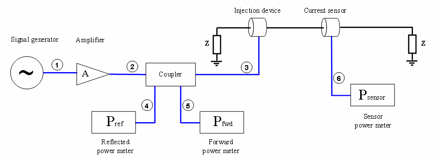
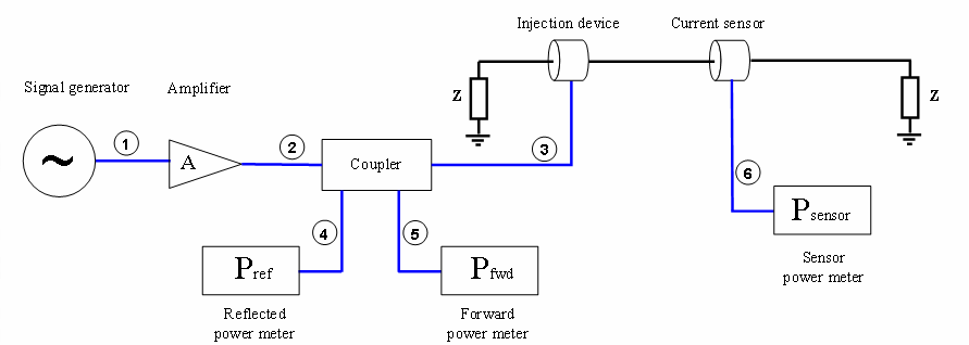
During conducted immunity tests according to the "current levelling" method, the injected current during the tests is real time levelled to the desired value. For "current levelling" tests, no calibration files are required. Some EMC standards, like automotive standards, describe current levelling test methods.
Some EMC standards prescribe the use of a selective power meter like a spectrum analyser. A selective power meter will only measure the fundamental frequency of the injected current, where a broad band power meter measures the fundamental frequency with all of its harmonics. On the other hand, a B.B. power meter is much more accurate than the amplitude accuracy of a spectrum analyser. RadiMation® supports both the use of spectrum analysers and power meters simply by selecting the corresponding power meter device driver.
| Device name | Tab in RadiMation® configuration window |
|---|---|
| Signal Generator | Standard 1 |
| Amplifier | Standard 1 |
| Coupler | Standard 1 |
| Power meter Pfwd | Standard 1 |
| Power meter Refl | Standard 1 |
| Injection device | Standard 2 |
| Current sensor | Standard 2 |
| Sensor power meter | Standard 2 |
| # | Device name | Tab in RadiMation® configuration window |
|---|---|---|
| 1 | Cable SG-> Amplifier | Cables |
| 2 | Cable Amplifier-> Coupler | Cables |
| 3 | Cable Coupler-> Antenna | Cables |
| 4 | Cable Coupler-> Fwd Power meter | Cables |
| 5 | Cable Coupler-> Refl Power Meter | Cables |
| 6 | Cable Current-> Power Meter | Cables |
| Note: | Usage of cable correction factors is not mandatory. However, using correction factors will increase measurement accuracy during immunity measurements.
When in doubt contact your reseller. |
Fixed Power method[edit]
Fixed generator tests can be useful during various kinds of EMC tests. During current injection tests, this method can be used to achieve the maximum injected current the amplifier is able to generate. Although this will not be a constant current over the frequency range, it can be useful during engineering work.
-
 Tests
Tests
-
 Conducted Immunity
-
 Fixed Power
-
-
-
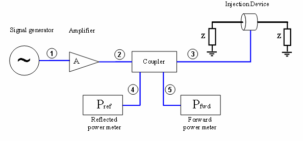
Fixed generator tests can be performed in three different ways:
Fixed signal generator output level. Tests with a fixed generator output level do not take cable losses and amplifier frequency response into account. No power meters are needed during these tests and therefore, the test speed is higher than the fixed forward and fixed transmitted power tests. Fixed Forward power level Tests with a fixed forward power level do take cable losses and amplifier frequency response into account. One power meter is required during these tests. This test method does not take VSWR mismatch between the amplifier and current probe into account (i.e.: the forward power and transfer impedance of the current probe alone is not enough to calculate the actually injected current). Tests with a fixed transmitted power level take cable losses, amplifier frequency response and VSWR mismatch into account. Two power meters are required during these tests, one to measure the forward power, and one to measure the reflected power. The difference between forward power and reflected power is the transmitted power.
| Device name | Tab in RadiMation® configuration window |
|---|---|
| Signal Generator | Standard 1 |
| Amplifier | Standard 1 |
| Coupler | Standard 1 |
| Power meter Pfwd | Standard 1 |
| Power meter Refl | Standard 1 |
| Injection device | Standard 2 |
| # | Device name | Tab in RadiMation® configuration window |
|---|---|---|
| 1 | Cable SG-> Amplifier | Cables |
| 2 | Cable Amplifier-> Coupler | Cables |
| 3 | Cable Coupler-> Antenna | Cables |
| 4 | Cable Coupler-> Fwd Power Meter | Cables |
| 5 | Cable Coupler-> Ref Power Meter | Cables |
| Note: | Usage of cable correction factors is not mandatory. However, using correction factors will increase measurement accuracy during immunity
measurements. When in doubt contact your reseller. |
Minimum performance method[edit]
The RadiMation® package also supports a specific method to determine the minimum performance level of a Device Under Test. This method differentiates itself from the aforementioned methods that is does not generate a fixed specified injected current but a varying injected current based on the susceptibility of the Device Under Test.
-
 Tests
Tests
-
 Conducted Immunity
-
 Minimum Performance
-
-
-
The method relies heavily on EUT monitoring (see chapter 8) to determine at which level the Device Under Test is influenced. Before the test is started the relevant A/D-channels have to be configured. Pushing the input button on the configuration screen does this.
The test is started at a (low) injection level after which the current is increased with a specified increment till either of both situations arises. The current is limited by amplifier protection or the Device Under Test will be influenced in such way that the specified limits are exceeded. The field strength is than reduced with a specified step and the software will change to the next frequency point. This test will result in a graph showing the level to which the Device Under Test is unaffected by a current injection.
| Device name | Tab in RadiMation® configuration window |
|---|---|
| Signal Generator | Standard 1 |
| Amplifier | Standard 1 |
| Coupler | Standard 1 |
| Power meter Pfwd | Standard 1 |
| Power meter Refl | Standard 1 |
| Injection device | Standard 2 |
| Current sensor | Standard 2 |
| Sensor power meter | Standard 2 |
| # | Device name | Tab in RadiMation® configuration window |
|---|---|---|
| 1 | Cable SG-> Amplifier | Cables |
| 2 | Cable Amplifier-> Coupler | Cables |
| 3 | Cable Coupler-> Antenna | Cables |
| 4 | Cable Coupler-> Fwd Power Meter | Cables |
| 5 | Cable Coupler-> Refl Power Meter | Cables |
| 6 | Cable Current-> Power Meter | Cables |
| Note: | The current sensor, the sensor power meter and cable only need to be inserted when current limiting is selected. When not selected usage of these devices will be omitted. |
| Note: | Usage of cable correction factors is not mandatory. However, using correction factors will increase measurement accuracy during immunity measurements.
When in doubt contact your reseller. |
Short cut keys in manual mode[edit]
The following short cut keys can be used during manual mode.
| Key | Function |
|---|---|
| Up | Carrier level up. |
| Down | Carrier level down. |
| Left | Carrier frequency down. |
| Right | Carrier frequency up. |
| N,n | Set carrier on. |
| F,f | Set carrier off. |
Tolerance[edit]
For every conducted immunity test you can define a tolerance. This tolerance has great effect on the measurement. If you choose the tolerance to large then the test results are not usable, if you choose the tolerance to small then it could be that RadiMation® has problems performing the test correctly. For example if you define a tolerance of 0.1 dB and your system is only capable of measuring with an uncertenty of 0.2dB than it could be you get a very large event log. So what does it really mean this tolerance? The best way is to explain by using an example. Suppose you are performing a fixed power test, leveling is set on netpower. You have told RadiMation® to generate 50 dBm with a tolerance of 0.2 dB. When RadiMation® is leveling the power it will accept any power level between 50 and 50.2 dBm as a correct leveled value, and will continue with the test.
