Rohde & Schwarz NRP-Z91
The Rohde & Schwarz NRP-Z91 device driver is a Power Meter which is supported by RadiMation®.
Configuration[edit]
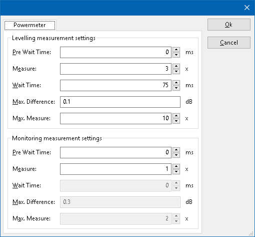
The following tabs are available in the advanced configuration of the Rohde & Schwarz NRP-Z91:
| Wait time before starting the measurement-loop. Can be used to wait for a signal generator, and or amplifier to stabilize. |
| The minimum amount of measurements in the measure loop. Continues to loop even if power level is stable. |
| The wait time between each measurement is taken, during the measurement-loop. |
| If the measured power between each measurement in the measurement-loop, is less than this value. The measured power is stable. The measurement-loop will then stop. |
| The maximum amount of measure times, for the measurement-loop |
According to these settings, RadiMation® will perform a minimum of 3 power measurements with a wait time between the measurements of 75ms. If all those 3 measurements are within 0.1 dB, the power measurement is assumed to be stable, and RadiMation® will continue to average of the last 3 measurements. If the difference between the measurements is larger than the specified 0.1 dB, an additional power measurement will be performed, and the last 3 samples will be compared to the 0.1 dB difference again. At most 10 measurements will be performed if the difference between the 3 samples will not be within the specified 0.1 dB.
Both for the leveling, and the monitoring these settings can be set individually. The leveling is used, whenever RadiMation® is measuring the power, to regulate the signal generator. If the powermeter is only used as input, without regulating on it, then the monitoring settings are used.
More detailed information on how to achieve a fast and stable power measurement is available in Application Note 106: Powermeter parameter configuration.
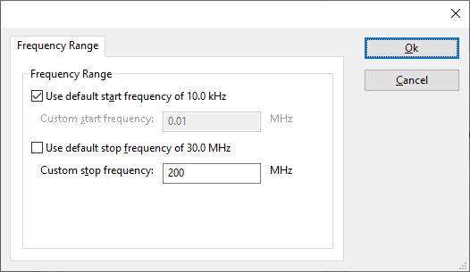
The frequency range of the Rohde & Schwarz NRP-Z91 as provided by the manufacturer is shown and selected as default. It is possible to overrule these frequencies and to manual adjust the allowed frequency range of the Rohde & Schwarz NRP-Z91.
| If the checkbox is checked, the default start frequency will be used as the lowest usable frequency in a test for this device. |
| If the Use default start frequency checkbox is unchecked, another start frequency (expressed in MHz) can be specified. The customized start frequency will then be used as the lowest usable frequency in a test for this device. The customized frequency can be a limitation or an extension of the default start frequency. |
| If the checkbox is checked, the default stop frequency will be used as the highest usable frequency in a test for this device. |
| If the Use default stop frequency checkbox is unchecked, another stop frequency (expressed in MHz) can be specified. The customized stop frequency will then be used as the highest usable frequency in a test for this device. The customized frequency can be a limitation or an extension of the default stop frequency. |
Specifying a different frequency range can be useful if for example:
- A device (like a coupler, antenna, injection device, cable, etc...) is still useable (but out of specification) outside the standard suggested frequency range.
- An external mixer is used to measure an extended frequency range.
- An up- or down-convertor is used to shift the frequency range.
- A newer model of a device is present that has an extended frequency range, and still uses the same remote control commands.
Be careful changing these setting as RadiMation® is no longer able to verify if the Rohde & Schwarz NRP-Z91 is used outside frequency range that is specified by the manufacturer. This may result to serious damage of your measurement device.
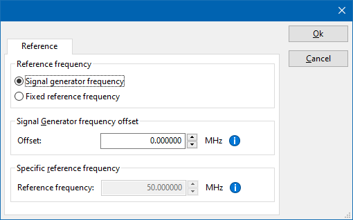
The settings on the Reference tab influence the measurement frequency that is communicated to the measurement device. The frequency that is forwarded to the measurement device can for example be used by the device to perform the measurement on the correct frequency, or use the correct internal frequency dependant correction or calibration factor on the measurement result. Normally it is desired that the measurement frequency is the same as the carrier frequency of the signal generator. In some situations it can however be required to communicate a different frequency to the measurement device. In such a situation the settings on the Reference tab can be modified.
| Selects that the actual carrier frequency of the signal generator is communicated to the measurement device. This is the default behaviour. |
| Selects that a fixed frequency (independent of the signal generator carrier frequency) is communicated to the measurement device. |
| An additional offset frequency specified in MHz, that is added to frequency that is communicated to the measurement device. This value can be positive or negative, and defaults to 0.0 MHz. |
| The fixed reference frequency specified in MHz that is communicated to the measurement device, when the Fixed reference frequency option is selected. |
| Warning: | When a different reference frequency is specified and communicated to the measurement device, it is only relevant for the measurement device. A correction file that is attached to the device driver in RadiMation® will still use the correction value that is specified for the actual signal generator carrier frequency. |
The Rohde & Schwarz NRP-Z91 is a power meter with a diode head connected by USB to the PC.
Notes[edit]
- The RadiMation® device driver can only be used if the program NRPView, 1.0.27 or above, from Rohde & Schwarz is installed. When installing the program make sure that you install all the items. If not all items are installed, some required dll's are not installed.
- Setting the resolution higher will make the measurement slower because the power meter is taking more samples and perform an average over the samples. this is done dynamically depending on the power measured.
- The syntax for the Instrument Descriptor is following:
USB::<vendor Id>::<product Id>::<serial number>
where <vendor Id> is 0AAD for Rohde&Schwarz
     <product Id> depends on the sensor
                      NRP-Z21    : 0x0003
                      NRP-FU     : 0x0004
                      FSH-Z1     : 0x000B
                      NRP-Z11    : 0x000C
                      NRP-Z22    : 0x0013
                      NRP-Z23    : 0x0014
                      NRP-Z24    : 0x0015
                      NRP-Z51    : 0x0016
                      NRP-Z52    : 0x0017
                      NRP-Z55    : 0x0018
                      NRP-Z56    : 0x0019
                      FSH-Z18    : 0x001A
                      NRP-Z91    : 0x0021
                      NRP-Z81    : 0x0023
                      NRP-Z31    : 0x002C
                      NRP-Z37    : 0x002D
                      NRP-Z96    : 0x002E
                      NRP-Z27    : 0x002F
                      NRP-Z28    : 0x0051
                      NRP-Z98    : 0x0052
                      NRP-Z92    : 0x0062
                      NRP-Z57    : 0x0070
                      NRP-Z85    : 0x0083
                      NRPC40     : 0x008F
                      NRPC50     : 0x0090
                      NRP-Z86    : 0x0095
                      NRP-Z41    : 0x0096
                      NRP-Z61    : 0x0097
                      NRP-Z71    : 0x0098
                      NRP-Z32    : 0x009A
                      NRP-Z211   : 0x00A6
                      NRP-Z221   : 0x00A7
                      NRP-Z58    : 0x00A8
                      NRPC33     : 0x00B6
                      NRPC18     : 0x00Bf
                      NRPC18-B1  : 0x00C1
                      NRPC33-B1  : 0x00C2
                      NRPC40-B1  : 0x00C3
                      NRPC50-B1  : 0x00C4
                      NRP8S      : 0x00E2
                      NRP8SN     : 0x0137
                      NRP18S     : 0x0138
                      NRP18SN    : 0x0139
                      NRP33S     : 0x0145
                      NRP33SN    : 0x0146
                      NRP18S-10  : 0x0148
                      NRP18SN-10 : 0x0149
                      NRP18S-20  : 0x014A
                      NRP18SN-20 : 0x014B
                      NRP18S-25  : 0x014C
                      NRP18SN-25 : 0x014D
                      NRP18A     : 0x014E
                      NRP18AN    : 0x014F
                      NRP18T     : 0x0150
                      NRP18TN    : 0x0151
                      NRP33T     : 0x0152
                      NRP33TN    : 0x0153
                      NRP40T     : 0x0154
                      NRP40TN    : 0x0155
                      NRP50T     : 0x0156
                      NRP50TN    : 0x0157
                      NRP67T     : 0x0158
                      NRP67TN    : 0x0159
                      NRP110T    : 0x015A
                      NRP40S     : 0x015F
                      NRP40SN    : 0x0160
                      NRP50S     : 0x0161
                      NRP50SN    : 0x0162
                      NRP33SN-V  : 0x0168
                      NRP6A      : 0x0178
                      NRP6AN     : 0x0179
                      NRPM3      : 0x0195
     <serial number>  you can find on your sensor. Serial number is number
                      with 6 digits. For example 900003
Examples: "USB::0x0AAD::0x000B::900003"
You can use '*' for <product Id> or <serial number>. We suggest to use fully qualified resource descriptors, when you have connected more than one sensor. You can use the asterisk placeholder, when only one sensor is connected.
Examples:
- "USB::0x0AAD::0x000C::*" - Opens first NRP-Z11 sensor on the USB bus
- "USB::0x0AAD::*" - Opens first R&S sensor on the USB bus
- "*" - Opens first R&S sensor on the USB bus
Related RadiMation errors[edit]
- RadiMation Error: -1074001424("Instrument status error"), when doing a zero of the power meter. the power on the head is too much, decrease the power and try again.
Installation[edit]
Please go the official website of the manufacturer Rohde & Schwarz and go to the page of your R&S®NRP Average Power Sensor model. [1]
Apparently the required component for this driver is the R&S® NRP-Toolkit. Install this toolkit first: https://cdn.rohde-schwarz.com/pws/dl_downloads/dl_software/exe/NRPToolkit-4.15.6675.13278.exe


