RadiMation Application Note 143
| Warning: | This application note is still work in progress. It is currently incomplete and could contain errors!! |
Using the Teseq NSG4060 low frequency immunity test system in RadiMation®[edit]
This RadiMation® application note explains how the Teseq NSG4060 can be used in combination with RadiMation® to perform testing accoording to the IEC 61000-4-16 and IEC 61000-4-19 standards.
The Teseq NSG4060 is a device that is designed for immunity testing in the frequency range of 15 Hz to 150 kHz, according the IEC 61000-4-16 and IEC 61000-4-19 standards. For more information regarding how to control, setup, configure and use the Teseq NSG4060, use the instructions as specified in the user manual of the Teseq NSG4060. All information of the Teseq NSG4060 is available at https://www.ametek-cts.com/products/brands/teseq/nsg-4060a
The most relevant specifications of the Teseq NSG4060 are:
| Minimal voltage | 0.0 Volt |
| Maximal voltage | 300.0 Volt |
| Voltage resolution | 0.01 Volt |
| Minimal frequency | DC |
| Maximal frequency | 150 kHz |
| Frequency resolution | 0.01 Hz |
Performing immunity measurement according to IEC 61000-4-16[edit]
The IEC 61000-4-16 describes how to perform immunity testing to test the susceptibility of an EUT while being exposed to common mode disturbance signals. These disturbance signals are generated by injecting a voltage into cables attached to the ports found on the EUT. These injected disturbance signals are able to influence the correct operation of the EUT. The IEC 61000-4-16 standard also describes which cables and port of applicable EUT's should be tested and the test parameters that should be used. These can be ports with cables transferring data or power to or from the EUT. The standards also describes how these tests should be setup regarding the used test components. Depending on the EUT or to be tested cables, CDN's or specific components must be connected or used during these tests.
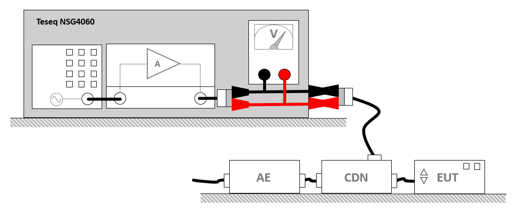
An often used test setup for this test would be:
In the situation that the Teseq NSG4060 is used, multiple individual components are housed in the Teseq NSG4060 itself.
Testsite configuration[edit]
The testsite configuration in RadiMation® should include the signal generator driver for the applicable generator. Another required driver is the amplifier driver for this generator. This driver can be also be used to increase the maximum voltage which the signal generator driver is able to regulate to, if necessary. More information regarding increasing the voltage limit is seen further down below.
In addition to these mentioned device drivers RadiMation® requires that a voltage measuring device driver is used. This multimeter device driver returns the voltage that is generated at the outpt of the amplifier back to RadiMation®. This is required to complete the voltage regulation loop used by RadiMation®. The voltage measuring device is added by selecting the Multimeter device driver for the applicable voltage generator in the test site.
For the Teseq NSG4060, these devices (the signal generator, amplifier and multimeter) are all physically present in the Teseq NSG4060 itself, but for RadiMation® these are still 3 individual instruments, and thus requires the 3 corresponding device drivers.
The configuration of the testsite should contain the following devices:
| Device name | Tab in testsite configuration window | Driver |
|---|---|---|
| Signal Generator | Devices 1 | Teseq NSG4060 |
| Amplifier | Devices 1 | Teseq NSG4060 |
| Multimeter | Devices 1 | Teseq NSG4060 |
| Injection Device | Devices 2 | depending on the used CDN |
Test configuration[edit]
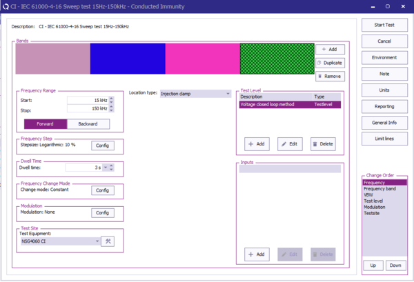
To perform the tests use a Conducted Immunity Multiband test by selecting from the menu:
-
 Tests
Tests
-
 Conducted Immunity
-
 Multiband
-
-
-
The complete test can be separated in multiple bands. The band configuration seen in this table is configured in the shown test configuration.
| Band # | Frequency Range | Frequency Step | Dwell time | Test level | Location type |
|---|---|---|---|---|---|
| Band 1 | 15 Hz - 150 Hz | logarithmic 10% | 3.0 s | 3.0 Volt | Injection clamp |
| Band 2 | 150 Hz - 1.5 kHz | logarithmic 10% | 3.0 s | 3.0 Volt | Injection clamp |
| Band 3 | 1.5 kHz - 15 kHz | logarithmic 10% | 3.0 s | 3.0 Volt | Injection clamp |
| Band 4 | 15 kHz - 150 kHz | logarithmic 10% | 3.0 s | 3.0 Volt | Injection clamp |
| The start frequency of the test. For example 15 kHz. |
| The stop frequency of the test. For example 150 kHz. |
| The frequency step that should be used to increment the frequency. For example 10 kHz. |
| The dwell time that should be used at every frequency. For example 2 seconds. |
| The mode that should be used to change from one frequency to the next frequency. |
| The modulation that should be applied during the dwell time at each frequency. |
| The name of the testsite that should be used. This testsite should at least have all the required equipment. |
| The type of test that should be used. |
| The configuration of the testlevels that should be used during the regulation of the test. |
| The configuration of additional inputs that should be measured during the test. |
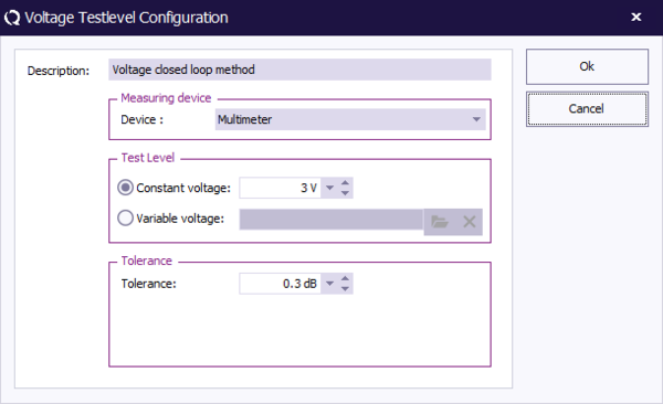
For the configuration of the testlevel a Voltage closed loop method should be used. This testlevel will ensure that the voltage as measured by the multimeter is regulated to the desired testlevel by changing the signal generator carrier level. In the testlevel configuration the Multimeter should be selected as the Measuring device.
| Specifies the name that should be used for this testlevel. |
| The measuring device which is used to regulate to the desired testlevel. |
| The desired testlevel for the voltage. |
| A correction file that should be used to for a frequency depending testlevel, which allows to do variation of the voltage over the frequency. |
| The tolerance (specified in dB) that should be used for the accuracy of the regulated testlevel. For example: 0.3 dB. |
When this test is started, the signal generator will be set to every frequency, and the signal generator carrier level is adjusted in such a way that the multimeter measures the actual generated and desired voltage testlevel. Once the EUT test is finished, the results of this test is stored in the EUT file, and available as one of the performed Tests in the EUT file. Selecting the corresponding test result and pressing on Info will show the test results again.
Conclusion[edit]
Because the Teseq NSG4060 is a product that houses several individual test and measurement devices, it is needed to specify different individual device drivers in RadiMation®. With the described configuration a Multiband Conducted Immunity test can be used in to control the Teseq NSG4060 to perform testing of low frequency disturbances.
Teseq NSG4060 levelling implementation details[edit]
For RadiMation® the Teseq NSG4060 is a test and measurement device that combines multiple individual test and measurement devices in the same housing. This does require that in RadiMation® multiple device drivers should be created, that cooperate to correctly control the complete Teseq NSG4060. The details concerning this combination of multiple device drivers is explained below.
Teseq NSG4060 signal generator[edit]
The Teseq NSG4060 generator is controlled as being a signal generator device driver. RadiMation® set the signal power of signal generators in dBm. The Teseq NSG4060 however behaves as a voltage generator requires that the signal level is set in Volt. To achieve this the driver for the Teseq NSG4060 signal generator is able to map the normally requested signal power in dBm to a signal level in dBV. As both dBm and dBV are logarithmic, the available dynamic range (100 dB) which RadiMation® uses to indicate the signal power starting from -100 dBm, can be translated to a similar dynamic range in which the possible dBV levels can be converted to allowed voltage levels to be set on the combined Teseq NSG4060.
Mapping between dBm and dBV levels[edit]
The mapping between dBm and dBV values for the Teseq NSG4060 is:
Usually RadiMation® starts levelling a signal generator from -30 dBm to 0 dBm. For the Teseq NSG4060 this result that at a signal power of -30 dBm, a voltage level of -20 dBV is being generated. This results in a level of 0.1 Volt to bet set on the output of the generator. The mapping between dBm and dBV has been selected in such a way that initial voltage set during regulation is not exceeding dangerous voltage values when the default signal generator start level is used.
The dynamic range of the Teseq NSG4060 generator has been selected to map signal power between -90 dBV and +10 dBV. This corresponds to a range of 0.0000316 Volt to 3.16 Volt. As the lowest voltage of the Teseq NSG4060 is 0.01 V, all values below -40 dBV are clipped to 0.0 V. This means that when RadiMation® requests a signal power of -50 dBm, it corresponds to -40 dBV, which is the lowest possible voltage level. Any RadiMation® signal generator carrier level lower than -50 dBm, will set the Teseq NSG4060 to generate 0.0 V. Regulation of the voltage is thus really started when the requested signal carrier level is higher than -50 dBm.
As the device supports testing up to 300 Volt in short duration tests, it will be possible to extend the dynamic range of the generator with +40 dB. This extension will make sure that a level of +50 dBV can be reached when the mapping from dBm to dBV values is performed. As extending the default signal generator dynamic range by +40 dB will result in a 140 dBm total range, which means that -90 dBV + 140 dB = +50 dBV can be reached. This will be atleast 300 Volt. More information on how to extend the maximum allowed signal generator power in RadiMation, see information further below.
This driver is configured to be used as the signal generator found in the active testsite.
NSG4060 MultiMeter[edit]
The NSG4060 generator itself does not require that a voltage regulation loop is "actively" measured to regulate to a requested voltage level. However, to use such a generator, RadiMation still needs to be aware of the current set/measured voltage.
To do this a MultiMeter device driver is available which is able to return the last voltage set on the generator, as being the "real" measured voltage. As the generator performs the internal leveling on its own, the returned voltage by the multimeter would be equal too the actual level set.
This driver is configured to be used as the multimeter found in the active testsite, and is selected as the used measuring device when configuring a voltage closed loop test level.
NSG4060 Amplifier[edit]
The NSG4060 generator has its own internal amplifier which is not actively controlled by RadiMation. However RadiMation does require that a amplifier driver is used in the testsite when performing immunity tests. No actual communication is done related to using this amplifier driver, it is only used to keep track of the expected amplifier state during the test.
Increasing the maximum Voltage
This NSG4060 Amplifier driver however, can be used to increase the maximum allowed signal input power.
Changing the maximum allowed signal power will result in reaching higher possible voltages using the NSG4060.
For more information regarding the maximum allowed signal power and input protection files see: https://wiki.radimation.com/wiki/index.php/Amplifier_Protection
This driver is configured to be used as the amplifier found in the active testsite.
Increasing the maximum generator voltage[edit]
It is possible to change the available dynamic range used to level the NSG4060 generator. Using the Amplifier signal input protection correction file, the limitation of signal power at 0 dBm can be increased to +20 dBm.
This will increase the highest possible voltage from +10 dBV to 30 dBV, which is ~31.6 Volt. A signal power of +20 dBm is currently the configured maximum signal power in RadiMation.
If 30 Volt is still not enough, this limit of +20 dBm signal power can be further increased by changing an advanced option in RadiMation. Using the increased max signal power limit, it is possible to further increase the Amplifier signal input protection to add the dynamic range required to reach the requested voltage.
For more information regarding the maximum allowed signal power and input protection files see: https://wiki.radimation.com/wiki/index.php/Amplifier_Protection


