RadiMation Application Note 154
How to perform a MIL-STD CS114, Conducted susceptibility, bulk cable injection test
This application note explains how the MIL-STD CS114, Conducted susceptibility, bulk cable injection test can be performed with RadiMation®
The exact requirements and test methods for the CS114 are specified in the MIL-STD-461.
Necessary equipment
The following devices are necessary to execute this test:
- Signal generator
- Amplifier
- Coupler
- Forward power meter
- Reflected power meter (optionally)
- Current sensor
- Sensor power meter / Analyser
- 50 Ohm load
- 50 Ohm attenuator
- LISN
- Current injection device
- Current injection calibration jig (Calibration fixture)
- Cable drivers with corrections
Configuration of the test sites
Calibration
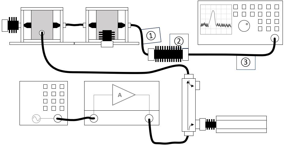
The configuration of the calibration test site should contain the following devices:
| Device name | Tab in testsite configuration window | note |
|---|---|---|
| Signal generator | Devices 1 | The signal generator to use |
| Amplifier | Devices 1 | The amplifier to use |
| Coupler | Devices 1 | The coupler to use |
| Forward power meter | Devices 1 | The forward power meter to use |
| Reflected power meter | Devices 1 | The reflected power meter to use (optionally) |
| Sensor power meter | Devices 2 | The power meter or analyser to use for measuring the current |
| Current sensor | Devices 2 | The current sensor to use with transfer factor attached to the driver |
| Injection device | Devices 2 | The injection clamp to use |
| Jig | Devices 2 | The jig to use |
| Cable current -> power meter | Cables | Cable (1) with a correction file specified for the cable loss |
| Cable current -> power meter | Cables | Cable (2) with the specified loss of the used attenuator |
| Cable current -> power meter | Cables | Cable (3) with a correction file specified for the cable loss |
Verification
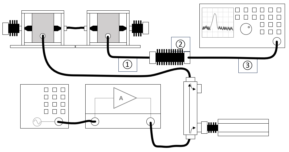
The configuration of the verification test site should contain the following devices:
| Device name | Tab in testsite configuration window | note |
|---|---|---|
| Signal generator | Devices 1 | The signal generator to use |
| Amplifier | Devices 1 | The amplifier to use |
| Coupler | Devices 1 | The coupler to use |
| Forward power meter | Devices 1 | The forward power meter to use |
| Reflected power meter | Devices 1 | The reflected power meter to use (optionally) |
| Sensor power meter | Devices 2 | The power meter or analyser to use for measuring the current |
| Current sensor | Devices 2 | The current sensor to use with transfer factor attached to the driver |
| Injection device | Devices 2 | The injection clamp to use |
| Cable current -> power meter | Cables | Cable (1) with a correction file specified for the cable loss |
| Cable current -> power meter | Cables | Cable (2) with the specified loss of the used attenuator |
| Cable current -> power meter | Cables | Cable (3) with a correction file specified for the cable loss |
EUT Testing
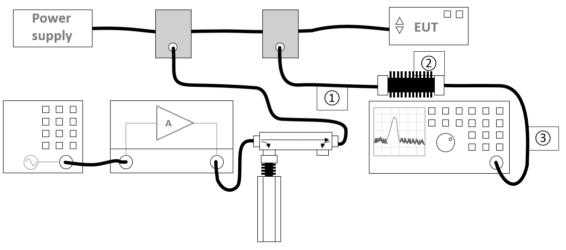
The configuration of the eut test site should contain the following devices:
| Device name | Tab in testsite configuration window | note |
|---|---|---|
| Signal generator | Devices 1 | The signal generator to use |
| Amplifier | Devices 1 | The amplifier to use |
| Coupler | Devices 1 | The coupler to use |
| Forward power meter | Devices 1 | The forward power meter to use |
| Reflected power meter | Devices 1 | The reflected power meter to use (optionally) |
| Sensor power meter | Devices 2 | The power meter or analyser to use for measuring the current |
| Current sensor | Devices 2 | The current sensor to use with transfer factor attached to the driver |
| Injection device | Devices 2 | The injection clamp to use |
| Cable current -> power meter | Cables | Cable (1) with a correction file specified for the cable loss |
| Cable current -> power meter | Cables | Cable (2) with the specified loss of the used attenuator |
| Cable current -> power meter | Cables | Cable (3) with a correction file specified for the cable loss |
Calibration procedure
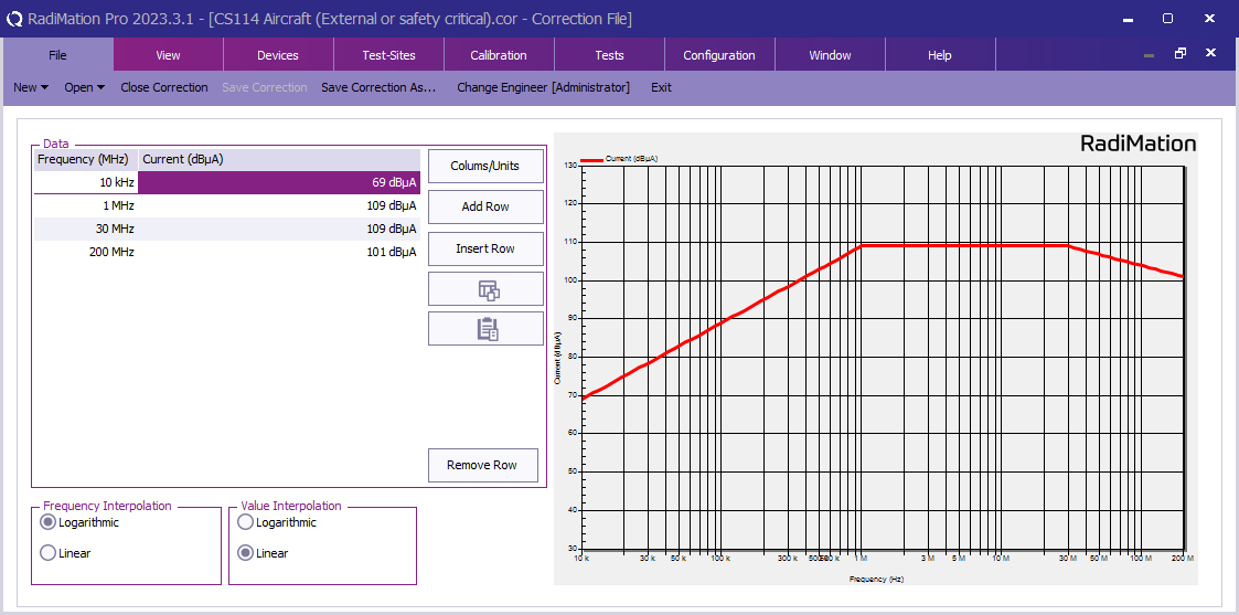
First create a correction file in RadiMation® and specify the applicable test level (See 'TABLE IV CS114 limit curves.' and 'FIGURE CS114-1. CS114 calibration limits.'). In this example the limits for 'Aircraft (External or safety critcal) / Curve 5 are configured.


