Teseq NSG 4070-80
The Teseq NSG 4070-80 device driver is a Power Meter which is supported by RadiMation®.
Configuration[edit]
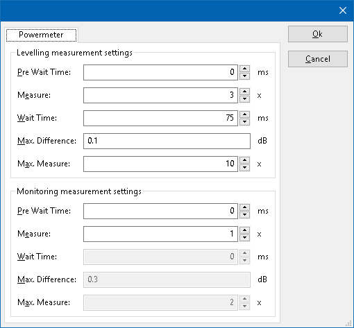
The following tabs are available in the advanced configuration of the Teseq NSG 4070-80:
| Wait time before starting the measurement-loop. Can be used to wait for a signal generator, and or amplifier to stabilize. |
| The minimum amount of measurements in the measure loop. Continues to loop even if power level is stable. |
| The wait time between each measurement is taken, during the measurement-loop. |
| If the measured power between each measurement in the measurement-loop, is less than this value. The measured power is stable. The measurement-loop will then stop. |
| The maximum amount of measure times, for the measurement-loop |
According to these settings, RadiMation® will perform a minimum of 3 power measurements with a wait time between the measurements of 75ms. If all those 3 measurements are within 0.1 dB, the power measurement is assumed to be stable, and RadiMation® will continue to average of the last 3 measurements. If the difference between the measurements is larger than the specified 0.1 dB, an additional power measurement will be performed, and the last 3 samples will be compared to the 0.1 dB difference again. At most 10 measurements will be performed if the difference between the 3 samples will not be within the specified 0.1 dB.
Both for the leveling, and the monitoring these settings can be set individually. The leveling is used, whenever RadiMation® is measuring the power, to regulate the signal generator. If the powermeter is only used as input, without regulating on it, then the monitoring settings are used.
More detailed information on how to achieve a fast and stable power measurement is available in Application Note 106: Powermeter parameter configuration.
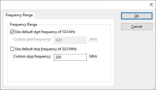
The frequency range of the Teseq NSG 4070-80 as provided by the manufacturer is shown and selected as default. It is possible to overrule these frequencies and to manually adjust the allowed frequency range of the Teseq NSG 4070-80.
| If the checkbox is checked, the default start frequency will be used as the lowest usable frequency in a test for this device. |
| If the Use default start frequency checkbox is unchecked, another start frequency (expressed in MHz) can be specified. The customized start frequency will then be used as the lowest usable frequency in a test for this device. The customized frequency can be a limitation or an extension of the default start frequency. |
| If the checkbox is checked, the default stop frequency will be used as the highest usable frequency in a test for this device. |
| If the Use default stop frequency checkbox is unchecked, another stop frequency (expressed in MHz) can be specified. The customized stop frequency will then be used as the highest usable frequency in a test for this device. The customized frequency can be a limitation or an extension of the default stop frequency. |
Specifying a different frequency range can be useful if for example:
- A device (like a coupler, antenna, injection device, cable, etc...) is still usable (but out of specification) outside the standard suggested frequency range.
- An external mixer is used to measure an extended frequency range.
- An up- or down-convertor is used to shift the frequency range.
- A newer model of a device is present that has an extended frequency range, and still uses the same remote control commands.
Be careful changing these settings as RadiMation® is no longer able to verify if the Teseq NSG 4070-80 is used outside frequency range that is specified by the manufacturer. This may result in serious damage to your measurement device.
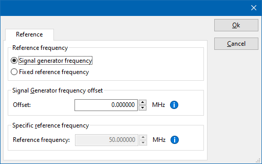
The settings on the Reference tab influence the measurement frequency that is communicated to the measurement device. The frequency that is forwarded to the measurement device can for example be used by the device to perform the measurement on the correct frequency, or use the correct internal frequency dependant correction or calibration factor on the measurement result. Normally it is desired that the measurement frequency is the same as the carrier frequency of the signal generator. In some situations it can however be required to communicate a different frequency to the measurement device. In such a situation the settings on the Reference tab can be modified.
| Selects that the actual carrier frequency of the signal generator is communicated to the measurement device. This is the default behaviour. |
| Selects that a fixed frequency (independent of the signal generator carrier frequency) is communicated to the measurement device. |
| An additional offset frequency specified in MHz, that is added to frequency that is communicated to the measurement device. This value can be positive or negative, and defaults to 0.0 MHz. |
| The fixed reference frequency specified in MHz that is communicated to the measurement device, when the Fixed reference frequency option is selected. |
| Warning: | When a different reference frequency is specified and communicated to the measurement device, it is only relevant for the measurement device. A correction file that is attached to the device driver in RadiMation® will still use the correction value that is specified for the actual signal generator carrier frequency. |
Links
- Google search: Teseq NSG 4070-80
- Google image search: Teseq NSG 4070-80
| This information about an equipment is automatically generated from the list of supported device drivers from RadiMation. |
| If you need more information you can contact radimation-support@raditeq.com. |
How to install and connect a NSG 4070 to Radimation over USB.[edit]
These amplifiers have diverse protocols to connect.
These are LAN (TCP/IP), RS232 and USB
This information regards the connection via USB. If you connect the device via USB it is important to know that it is RS232 over USB. In the documentation of the amplifier it is not very clear, however it is needed to understand and helps to configure the device in Radimation.
- Make sure that the device is set to USB. You can find this via the setup button on the device itself. Please reerence te manual from Teseq for further information.
- Connect the device physically via USB.
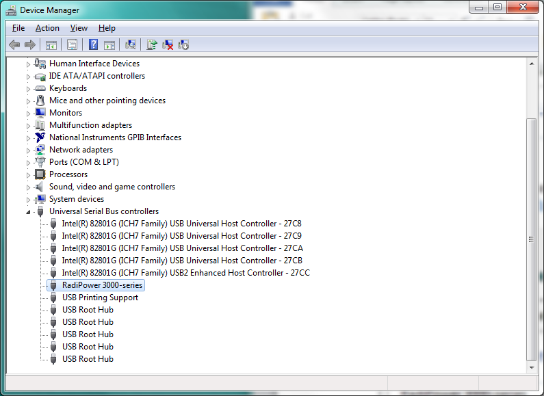
- Open device manager (Type device manager in the search window next to start in windows)
- Open your com ports and look for the name NSG 4070 (The picture above is a example. When the NSG4070 is present and recognised a com port with the name NSG 4070 should be visible here. If not please reference the manual from the device)
- Check which com port this is
- Open Radimation
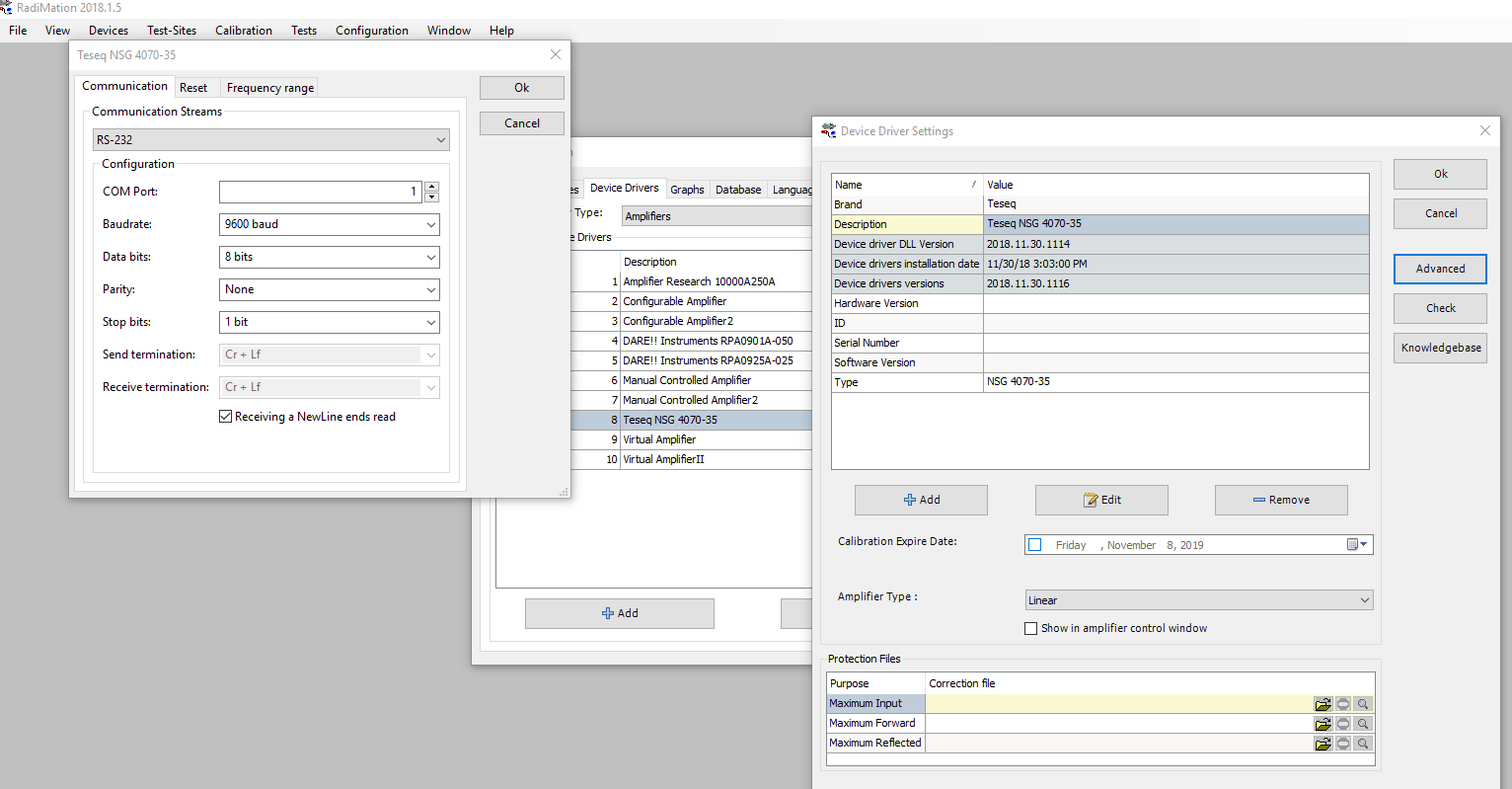
- Go to configuration/configuration/device drivers/amplifiers
- Add the driver for the NSG4070 by clicking add
- Open the settings by double clicking
- Click "advanced"
- Go to the tab "communication"
- Set "Communication streams" to: RS232
- Set the COM port to the number that you have found in device manager from Windows
- Set the Baud rate to 9600 baud !! (this is important, it is not in the documentation of the manufacturer. If you want to use the USB connection then it's communication is using RS-232 with a fixed baud rate of 96000)
- Leave the rest default.
- Click "Ok" and press "Check"
- If all was set correctly you will receive a message that the communication was successful. The amplifier is now configured and ready for use in the software
