Chapter 10
EUT monitoring and control[edit]
Input Channels[edit]
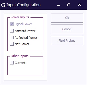
The input configuration is selected by pushing the “Input” button in the TSF window of an immunity test. A window like the one shown below will appear.
Goal[edit]
The input channels of the RadiMation® software are implemented to monitor output signals of the EUT as a function of the test frequency. The software is able to monitor each channel before, during and after each test frequency. This way of data storage is useful during certification tests as well as during the development process of a product.
The inputs channels allow automatic and accurate monitoring of EUT performance. Together with the output channels, full automatic tests can be performed without intervention of the test engineer.
The “before field” data of each input channel, tells you if the equipment is functioning properly before each test point. The “during field” data of each input channel records if the equipment is influenced during period the test signal is applied.
The “before field” graph will record all instability and/or drift of the EUT, where the “during field” graph will record both the instability and/or drift of the EUT and any influence of the EUT by the RF field.
The Software is able to support a maximum of 8 A/D converters with a maximum resolution of 16 bits. For each A/D channel, two graphs can be recorded (before field and during field graph). As an alternative, RadiMation® can also read data from oscilloscopes, audio analysers etc and use it as an A/D input signal. In this case, the operator should select the device driver for the measurement device (for example the oscilloscope) under A/D converter device driver in the equipment list.
The analogue channels can be used to monitor analogue voltages, currents, temperature, tacho generators etc. With some extra tools like opto couplers LED’s of the EUT can be monitored. Apart from the AD converters, “Field sensors”, forward power, reflected power and “current probes can be used as input.
AD channel Configuration[edit]
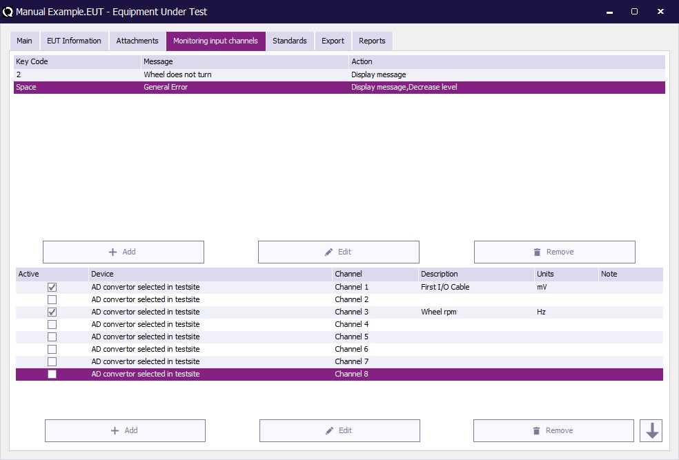
The input channels are configurated under the “AD Input, configuration menu” in the EUT window. This menu is entered by using the “AD-channel” tab in the EUT window. In the “AD Input, configuration menu” each A/D channel can be switched on and off separately. If a channel is switched on, the following items can be configurated in the set-up menu of that channel:
File:AD Channel Setup Window.jpg
| Under Description, a title can be applied to the corresponding A/D channel. The title may have a maximum length of 40 characters. |
| Under “Units” the units of the measured value can be entered. The entered units are only used as a label in the corresponding graph. |
| Under “Min. Input / Max. Input” the minimum and maximum scale values of the graphic are entered. |
| Warning: | This setting does not change the input range of the A/D converter. |
Example:
If an A/D converter is used with a maximum input range of 1 V and an external shunt resistor of 0.1 Ohm is used, the A/D configuration menu is set-up as the following:
Units : [A]
Min. Input : 0
Max. Input : 0.1
The graph will be displayed with a scale from 0 to 0.1 A on the Y- scale, and the frequency on the X- scale (from the start frequency tot the stop frequency as entered under the test configuration menu).
| The option “Note” allows text notes to be added to each A/D channel. This text field can be used to describe test conditions or the response of the EUT during the tests. The text fields can be changed after the test is completed under the “Info” screen. |
| The selection(s) under “Measure” determine under which conditions the A/D channel is measured. The “Before Field” graphic is measured before the test signal is applied at each test frequency. The “During Field” graphic is measured at the end of the “Dwell time”, during the period the test signal is applied. |
| When selecting a minimum or a maximum “Range”, RadiMation® can react if an A/D-channel is out of range. For example during a Radiated immunity test, the field generated can influence an EUT. RadiMation® can detect this and level the field back to a point that the EUT is not influenced any more. When no “Range” is selected, the A/D-channel is used for recording only. |
| Warning: | While reading each A/D channel will take a little time, scanning 8 A/D channels in the 2 modes for each test point will increase the total test time. Therefore we recommend switching off all unused A/D channels. |
Furthermore, drawing the graphs on the screen will also take some time. For maximum performance, do not leave all graphs open on the screen.
Field sensors[edit]
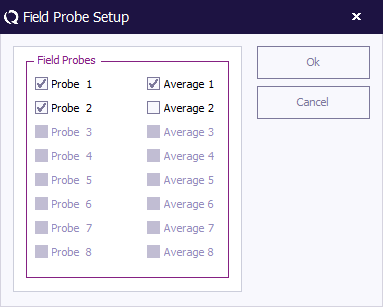
During a substitution test, a field sensor can be used to record the field strength near the EUT and record it in a graph. It should be noted that the presence of the EUT in the chamber will influence the field homogeneity in the close vicinity of the EUT. Therefore, the field sensor will probably not give the same reading as it would give in an empty chamber. The field sensor reading should therefore only be used as an indication.
Current probes[edit]
Current injection tests are more easily carried out and are less expensive than tests in an anechoic chamber (caused by the very expensive test equipment needed for radiated immunity tests).
Product improvements on an EUT therefore are more easily performed with a current injection set-up . For this purpose, during a substitution test, a current sensor can be used to record the RF current in one of the I/O cables of the EUT. RadiMation® can record the injected current in this cable due to the applied field.
This current sensor data can be used to simulate the influence to the EUT, in a current injection test set-up.
To get accurate current values, the current probe should be connected through a fibre optic cable in stead of using a coaxial cable. A coax cable will cause common-mode currents to flow on the screen, resulting in inaccurate test results.


