Difference between revisions of "Current sensor transfer impedance determination method"
| Line 1: | Line 1: | ||
| + | = Theory = | ||
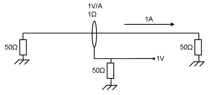
[[Image:Current sensor Transfer impedance Prove.PNG]] | [[Image:Current sensor Transfer impedance Prove.PNG]] | ||
| + | The left impedance is the signal generator which is generating enough power for 1 ampere. | ||
| + | This 1Amp. generates <math>P = I^2*R=50 \ Watt</math> in the right impedance. | ||
| + | |||
| + | The current sensor has 1 ohm transfer impedance, this means 1 ampere generates 1 Volt on the measuring part below. | ||
| + | |||
| + | The power in the lower 50 ohm impedance is <math>P = \frac{U^2}{R} = 20 \ mWatt</math> | ||
| + | |||
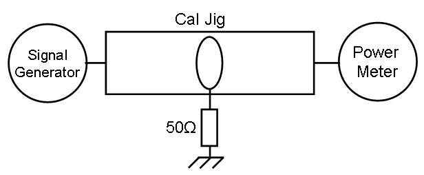
| + | = Reference measurement = | ||
[[Image:Current sensor Transfer impedance Ref measurement.PNG]] | [[Image:Current sensor Transfer impedance Ref measurement.PNG]] | ||
| + | |||
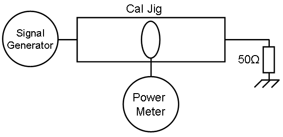
| + | = Probe measurement = | ||
[[Image:Current sensor Transfer impedance final measurement.PNG]] | [[Image:Current sensor Transfer impedance final measurement.PNG]] | ||
| + | |||
| + | = Calculation = | ||
| + | <Math>Correction \ factor (dB)= P_{Measured} - P_{Reference} + 33.98</Math> | ||
| + | |||
| + | <Math>P_{Measured}</Math> and <Math>P_{Reference}</Math> in dBm. | ||
{{note|This method is not a replacement for a real calibration.}} | {{note|This method is not a replacement for a real calibration.}} | ||
Revision as of 15:19, 23 January 2009
Theory
The left impedance is the signal generator which is generating enough power for 1 ampere.
This 1Amp. generates in the right impedance.
The current sensor has 1 ohm transfer impedance, this means 1 ampere generates 1 Volt on the measuring part below.
The power in the lower 50 ohm impedance is
Reference measurement
Probe measurement
Calculation
and in dBm.


