Difference between revisions of "File:HarmonicsSpectrumAnalyserAndAntennasEquipment.png"
(Joro uploaded a new version of File:HarmonicsSpectrumAnalyserAndAntennasEquipment.png) |
(→Summary) |
||
| Line 1: | Line 1: | ||
== Summary == | == Summary == | ||
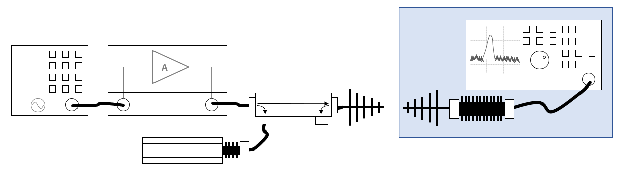
Shows a schematic diagram of the measurement setup for the harmonics calibration, where a receiving antenna is used for the measurement of the field harmonics. | Shows a schematic diagram of the measurement setup for the harmonics calibration, where a receiving antenna is used for the measurement of the field harmonics. | ||
| + | |||
| + | The blue area contains the equipment that should be able to measure the higher frequencies of the harmonics. | ||
Latest revision as of 09:54, 27 June 2022
Summary
Shows a schematic diagram of the measurement setup for the harmonics calibration, where a receiving antenna is used for the measurement of the field harmonics.
The blue area contains the equipment that should be able to measure the higher frequencies of the harmonics.
File history
Click on a date/time to view the file as it appeared at that time.
| Date/Time | Thumbnail | Dimensions | User | Comment | |
|---|---|---|---|---|---|
| current | 09:54, 27 June 2022 | 1,222 × 344 (23 KB) | Joro (talk | contribs) | The blue area contains the equipment that should be able to measure the higher frequencies of the harmonics. | |
| 14:14, 24 June 2022 | 1,208 × 316 (22 KB) | Joro (talk | contribs) | Shows a schematic diagram of the measurement setup for the harmonics calibration, where a receiving antenna is used for the measurement of the field harmonics. |
- You cannot overwrite this file.
File usage
The following page links to this file: