File:HarmonicsSpectrumAnalyserAndAntennasEquipment.png
Revision as of 09:54, 27 June 2022 by Joro (talk | contribs) (Joro uploaded a new version of File:HarmonicsSpectrumAnalyserAndAntennasEquipment.png)

Size of this preview: 800 × 213 pixels. Other resolutions: 320 × 85 pixels | 1,332 × 354 pixels.
Original file (1,332 × 354 pixels, file size: 29 KB, MIME type: image/png)
Summary
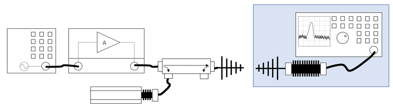
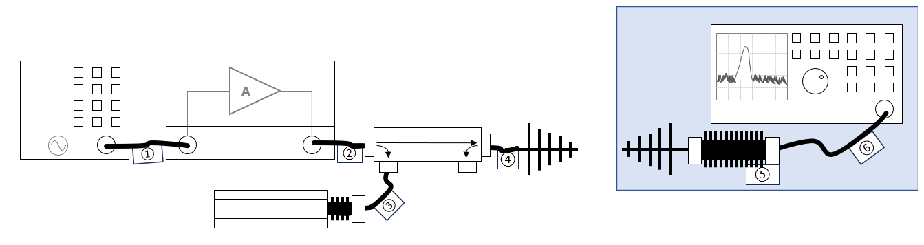
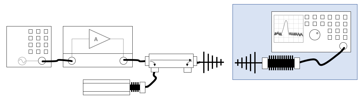
Shows a schematic diagram of the measurement setup for the harmonics calibration, where a receiving antenna is used for the measurement of the field harmonics.
File history
Click on a date/time to view the file as it appeared at that time.
| Date/Time | Thumbnail | Dimensions | User | Comment | |
|---|---|---|---|---|---|
| current | 11:26, 30 July 2024 | 1,332 × 354 (29 KB) | Joro (talk | contribs) | Removed label (4) between the coupler and the antenna as it is not used by the harmonic calibration | |
| 10:13, 30 July 2024 | 1,343 × 356 (29 KB) | Joro (talk | contribs) | Added cable tags to the cables | ||
| 09:54, 27 June 2022 | 1,222 × 344 (23 KB) | Joro (talk | contribs) | The blue area contains the equipment that should be able to measure the higher frequencies of the harmonics. | ||
| 14:14, 24 June 2022 | 1,208 × 316 (22 KB) | Joro (talk | contribs) | Shows a schematic diagram of the measurement setup for the harmonics calibration, where a receiving antenna is used for the measurement of the field harmonics. |
- You cannot overwrite this file.
File usage
The following page links to this file: