File:HarmonicsSpectrumAnalyserAndPowermeterEquipment.png
Size of this preview: 800 × 274 pixels. Other resolutions: 320 × 110 pixels | 1,022 × 350 pixels.
Original file (1,022 × 350 pixels, file size: 20 KB, MIME type: image/png)
Summary
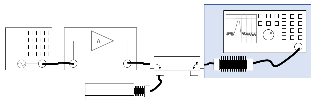
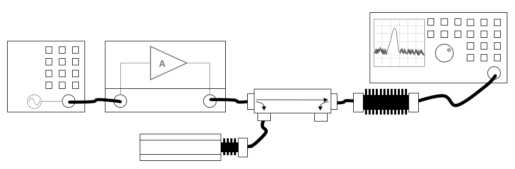
Shows a schematic diagram of the harmonics measurement using a broadband forward power meter and a spectrum analyser connected by an attenuator to the output of the amplifier.
The blue area contains the equipment that should be able to measure the higher frequencies of the harmonics.
File history
Click on a date/time to view the file as it appeared at that time.
| Date/Time | Thumbnail | Dimensions | User | Comment | |
|---|---|---|---|---|---|
| current | 09:53, 27 June 2022 | 1,022 × 350 (20 KB) | Joro (talk | contribs) | The blue area contains the equipment that should be able to measure the higher frequencies of the harmonics. | |
| 13:59, 24 June 2022 | 1,006 × 331 (20 KB) | Joro (talk | contribs) | Shows a schematic diagram of the harmonics measurement using a broadband forward power meter and a spectrum analyser connected by an attenuator to the output of the amplifier. |
- You cannot overwrite this file.
File usage
The following page links to this file: