Difference between revisions of "RadiMation Application Note 120"
(→Reference measurement) |
(→EUT measurement) |
||
| Line 31: | Line 31: | ||
During the Attenuation/Gain EUT calibration, the already performed system calibration also should be selected. And because the system calibration is known, the results of this EUT Calibration is already corrected with the measurement results of the system calibration. The reported EUT attenuation thus already is the desired attenuation coupling. | During the Attenuation/Gain EUT calibration, the already performed system calibration also should be selected. And because the system calibration is known, the results of this EUT Calibration is already corrected with the measurement results of the system calibration. The reported EUT attenuation thus already is the desired attenuation coupling. | ||
| − | + | [[File:HV-LVAttenuationGainEUTCalibration.png]] | |
| + | |||
<picture of the system attenuation/gain calibration with the correct settings> | <picture of the system attenuation/gain calibration with the correct settings> | ||
Revision as of 12:54, 10 April 2019
Contents
How to measure the HV-LV coupling attenuation
This RadiMation® application note explains how the high-voltage (HV) to low-voltage (LV) Coupling attenuation can be measured with RadiMation®. This HV-LV coupling attenuation is needed for several automotive standards, for example the BMW GS 950002-3:2015-12 or the CISPR 25:2016-10
Measurement of HV-LV coupling attenuation
The title of the BMW GS 95002-3 is: Motor Vehicles Electromagnetic Compatibility (EMC) Requirements and tests on components above 60 V nominal voltage.
The HV-LV coupling attenuation measurement as it is described in these standards, have the purpose to determine the coupling of components that are connected to the high voltage (above 60 V) system and the low voltage system of a motor vehicle.
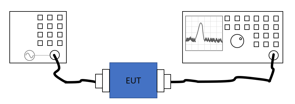
The principle of this measurement is that an EUT is connected on one side to the LV network and on the other side to the HV network. Then an attenuation measurement should be performed to the determine the coupling between the HV and LV networks that is caused by EUT.
This measurement can be done with two different methods:
- using a Vector Network Analyzer
- using a signal generator, amplifier and spectrum analyzer
In this application not we will explain how to perform the measurement using the signal generator method, because that type of equipment is more often available.
Reference measurement
To accurately perform the measurement, first a reference measurement is needed to determines the attenuation of the system setup, without the EUT present. This thus accurately determines the loss of the used cables and artificial networks.
This measurement can be performed in RadiMation by using the Attenuation/Gain system calibration.
<picture of the system attenuation/gain calibration with the correct settings>
EUT measurement
Once the Attenuation/Gain system calibration has been performed, and thus the reference measurement is known, the EUT can be installed and connected in the measurement setup. Then the coupling of the EUT between the HV and LV networks should be determined. This measurement can be performed in RadiMation by using the Attenuation/Gain EUT Calibration.
During the Attenuation/Gain EUT calibration, the already performed system calibration also should be selected. And because the system calibration is known, the results of this EUT Calibration is already corrected with the measurement results of the system calibration. The reported EUT attenuation thus already is the desired attenuation coupling.
<picture of the system attenuation/gain calibration with the correct settings>
Reporting
Explain that the following graphs can be shown
- reference sweep
- EUT sweep
- HV-LV attenuation coupling
<picture that shows the correct data....>
Conclusion
Acoording the CISPR25:2016-10 (as specified in Annex I), conducted emission measurements should be performed, where the determined HV-LV coupling attenuation has influence on the limits that should be used during the conducted emission measurements on the HV system. Based on the determined HV-LV coupling the correct limit should be determined, and then a normal conducted emission measurement can be performed with RadiMation®.

