Difference between revisions of "RadiMation Application Note 120"
(→EUT measurement) |
|||
| Line 45: | Line 45: | ||
== EUT measurement == | == EUT measurement == | ||
Once the Attenuation/Gain system calibration has been performed, and thus the reference measurement is known, the EUT can be installed and connected in the same measurement setup. | Once the Attenuation/Gain system calibration has been performed, and thus the reference measurement is known, the EUT can be installed and connected in the same measurement setup. | ||
| + | |||
| + | The converter between the coax cable and the HV port or LV port of the EUT, are depending on the connectors used by the EUT, and should probably be custom made, but should be designed in such way that they have a low as possible attenuation. | ||
| + | |||
| + | [[File:HV-LVAttenuationGainEUTCalibration.png]] | ||
| + | |||
Then the coupling of the EUT between the HV and LV networks should be determined. This measurement can be performed in {{RadiMation}} by using the Attenuation/Gain EUT Calibration. | Then the coupling of the EUT between the HV and LV networks should be determined. This measurement can be performed in {{RadiMation}} by using the Attenuation/Gain EUT Calibration. | ||
During the configuration Attenuation/Gain EUT calibration, the previously performed system calibration should be selected. And because the system calibration is selected, the results of the EUT Calibration are automatically corrected with the measurement results from the system calibration. The reported EUT attenuation thus already is the desired attenuation coupling. | During the configuration Attenuation/Gain EUT calibration, the previously performed system calibration should be selected. And because the system calibration is selected, the results of the EUT Calibration are automatically corrected with the measurement results from the system calibration. The reported EUT attenuation thus already is the desired attenuation coupling. | ||
| − | |||
| − | |||
In {{RadiMation}} when an EUT calibration itself is performed, first an EUT file needs to be opened. Once an EUT file is opened, the Attenuation/Gain measurement for the EUT can be started by selecting from the menu: | In {{RadiMation}} when an EUT calibration itself is performed, first an EUT file needs to be opened. Once an EUT file is opened, the Attenuation/Gain measurement for the EUT can be started by selecting from the menu: | ||
{{Menu|Calibration|EUT Calibration|Attenuation / Gain}} | {{Menu|Calibration|EUT Calibration|Attenuation / Gain}} | ||
| − | In the Attenuation EUT Calibration dialog, only the previously created calibration file should be selected in the {{ScreenElement|System Calibration}} field. All the other settings will be selected | + | In the Attenuation EUT Calibration dialog, only the previously created system calibration file should be selected in the {{ScreenElement|System Calibration}} field. All the other settings will be retrieved from the selected Attenuation/Gain System calibration file. |
| − | This then results in the following configuration of the Attenuation EUT Calibration: | + | This then for example results in the following configuration of the Attenuation EUT Calibration: |
[[File:HV-LVCouplingAttenuationEUTCalibrationTSF.png]] | [[File:HV-LVCouplingAttenuationEUTCalibrationTSF.png]] | ||
| − | When this calibration is started, the signal generator will be set to every frequency again, and the generated power will be also be measured by the spectrum analyzer. | + | When this EUT calibration is started, the signal generator will be set to every frequency again, and the generated power will be also be measured by the spectrum analyzer. |
| − | Once the EUT calibration is finished, the results of this EUT Calibration is stored in the EUT file, and available as one of the performed {{ScreenElement|Tests}}. Selecting the corresponding test | + | Once the EUT calibration is finished, the results of this EUT Calibration is stored in the EUT file, and available as one of the performed {{ScreenElement|Tests}} in the EUT file. Selecting the corresponding test result and pressing on {{ScreenElement|Info}} will show the EUT Calibration test result. |
| − | The measured attenuation during the EUT calibration (which is the injected signalpower minus the measured forwardpower) is compared to the attenuation that was measured during the system calibration, and the real attenuation of the EUT is then | + | The measured attenuation during the EUT calibration (which is the injected signalpower minus the measured forwardpower) is compared to the attenuation that was measured during the system calibration, and the real attenuation of the EUT is then calculated by subtracting those values. |
<math>Attenuation_{HV-LV} = Attenuation_{EUT} = (Signalpower_{EUT} - Forwardpower_{EUT}) - (Signalpower_{system} - Forwardpower_{system})</math> | <math>Attenuation_{HV-LV} = Attenuation_{EUT} = (Signalpower_{EUT} - Forwardpower_{EUT}) - (Signalpower_{system} - Forwardpower_{system})</math> | ||
Revision as of 19:19, 10 April 2019
Contents
How to measure the HV-LV coupling attenuation
This RadiMation® application note explains how the high-voltage (HV) to low-voltage (LV) Coupling attenuation can be measured with RadiMation®. This HV-LV coupling attenuation is needed for several automotive standards, for example the BMW GS 950002-3:2015-12 or the CISPR 25:2016-10
HV-LV coupling attenuation
The title of the BMW GS 95002-3 is: Motor Vehicles Electromagnetic Compatibility (EMC) Requirements and tests on components above 60 V nominal voltage.
The HV-LV coupling attenuation measurement as it is described in these standards, is designated for components that are connected to the high voltage (above 60 V) system and the low voltage system of a motor vehicle, and has the purpose to determine the coupling between the two voltage systems through the component.
The principle of this measurement is that a component (the EUT) is connected on one side to the LV network and on the other side to the HV network. Then an attenuation measurement should be performed to the determine the coupling between the HV and LV networks that is caused by EUT.
This measurement can be done with two different methods:
- using a Vector Network Analyzer
- using a signal generator and spectrum analyzer (optionally using an amplifier)
In this application note we will explain how to perform the measurement using the signal generator method, because that type of equipment is more often available.
Reference measurement (system calibration)
To improve the accuracy of the final attenuation measurement, first a reference measurement is needed to determine the intrinsic attenuation of the system setup, without the EUT present. This thus accurately determines the attenuation of the used cables, any used artificial networks, other used equipment, and the amplitude difference between the signal generator and the spectrum analyzer. This reference measurement is therefor also often called the system calibration.
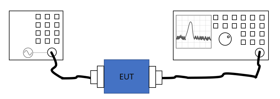
This reference measurement can be performed in RadiMation® by using the Attenuation/Gain system calibration. In a setup where a spectrum analyzer or receiver is used to perform the measurement of the generated signal, the setup is:
In RadiMation® then the system calibration can be started by selecting from the menu:
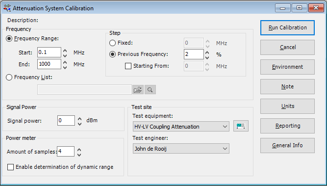
In the Attenuation System Calibration dialog, the required settings can be configured. The used standard often specifies most of these settings. This can for example be:
- Start: 0.1 MHz
- End: 1000 MHz
- Previous Frequency: 2 %, which will then use a logarithmic step with a frequency increment that is 2 % of the previous frequency.
- Signal power: 0 dBm, for a generated signal carrier level of 0 dBm.
- Amount of samples: 4, which will perform 4 power measurements on every frequency, and will use the average of those 4 samples, as the result on that frequency.
- Enable determination of dynamic range: Off, to disable that the maximum possible measurable attenuation is determined.
- Test equipment: The name of the testsite that should be used. This testsite should at least have a selected signal generator and a selected forward powermeter. The device that is selected as the forward powermeter in the testsite will be used as the measurement device.
This then results in the following configuration of the Attenuation System Calibration:
When this system calibration is started, the signal generator will generate every frequency, and the generated power will be measured by the spectrum analyzer. At the end of the system calibration a 'Save Calibration As' dialog is shown, which allows to save the result of the calibration to a .CAL calibration file. It is advised to specify a useful location and filename for this system calibration file, so it clearly identifies the purpose and reason of the system calibration.
EUT measurement
Once the Attenuation/Gain system calibration has been performed, and thus the reference measurement is known, the EUT can be installed and connected in the same measurement setup.
The converter between the coax cable and the HV port or LV port of the EUT, are depending on the connectors used by the EUT, and should probably be custom made, but should be designed in such way that they have a low as possible attenuation.
Then the coupling of the EUT between the HV and LV networks should be determined. This measurement can be performed in RadiMation® by using the Attenuation/Gain EUT Calibration.
During the configuration Attenuation/Gain EUT calibration, the previously performed system calibration should be selected. And because the system calibration is selected, the results of the EUT Calibration are automatically corrected with the measurement results from the system calibration. The reported EUT attenuation thus already is the desired attenuation coupling.
In RadiMation® when an EUT calibration itself is performed, first an EUT file needs to be opened. Once an EUT file is opened, the Attenuation/Gain measurement for the EUT can be started by selecting from the menu:
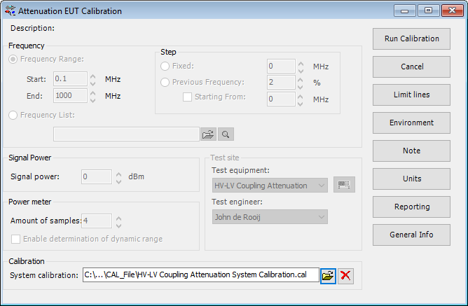
In the Attenuation EUT Calibration dialog, only the previously created system calibration file should be selected in the System Calibration field. All the other settings will be retrieved from the selected Attenuation/Gain System calibration file.
This then for example results in the following configuration of the Attenuation EUT Calibration:
When this EUT calibration is started, the signal generator will be set to every frequency again, and the generated power will be also be measured by the spectrum analyzer. Once the EUT calibration is finished, the results of this EUT Calibration is stored in the EUT file, and available as one of the performed Tests in the EUT file. Selecting the corresponding test result and pressing on Info will show the EUT Calibration test result.
The measured attenuation during the EUT calibration (which is the injected signalpower minus the measured forwardpower) is compared to the attenuation that was measured during the system calibration, and the real attenuation of the EUT is then calculated by subtracting those values.
Reporting
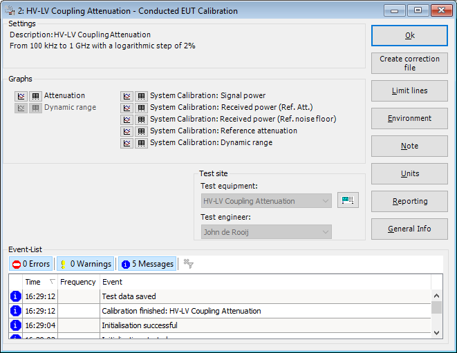
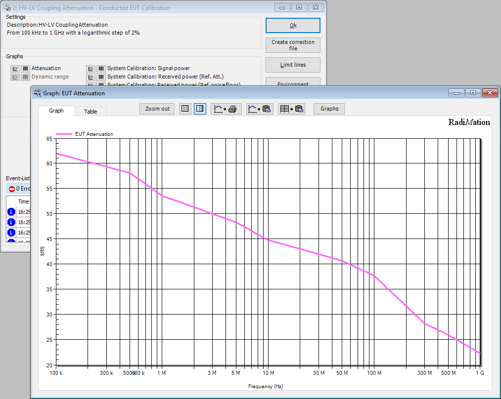
For the reviewing of the measurement result or the generation of the report, the different measurement results can be accessed and used. Open the test results of the EUT Calibration, which shows the Attenuation/Gain result window:
The following graphs are available from this window:
- Attenuation: The real attenuation of the EUT, already corrected with the reference attenuation that was determined during the system calibration
- Dynamic Range: The possible maximum attenuation that can be measured with the used test and measurement equipment
- System Calibration: Signal power: The signal power level that was used during the system calibration.
- System Calibration: Received power (Ref. Att.): The reading of the forward powermeter during the system calibration, when the carrier level of the signal generator was active
- System Calibration: Received power (Ref. noise floor): The reading of the forward powermeter during the system calibration, when the carrier level of the signal generator was turned off. This value is used to determine the possible dynamic range
- System Calibration: Reference attenuation: The attenuation that was calculated during the system calibration.
- System Calibration: Dynamic range: The possible maximum attenuation that can be measured with the used test and measurement equipment
The Attenuation graph is the most important graph because it specifies the determined real attenuation of the EUT, which is the HV-LV Attenuation coupling that is requested.
Conclusion
Some standards describe that the HV-LV coupling attenuation should be determined between different combinations of lines. That can be achieved by performing the above procedure multiple times where the line on which the signal generator or spectrum analyzer is connected is different. These EUT Calibrations can then all be performed in the same EUT file. The Note of the test results can the be used to specify which combination of lines is measured.
According the CISPR25:2016-10 (as specified in Annex I), conducted emission measurements should be performed, where the determined HV-LV coupling attenuation has influence on the limits that should be used during the conducted emission measurements on the HV system. Based on the determined HV-LV coupling the correct limit should be determined, and then a normal conducted emission measurement can be performed with RadiMation®.

