Difference between revisions of "RadiMation Application Note 138"
(→Calibration) |
(→Closed loop regulation) |
||
| Line 105: | Line 105: | ||
=== Closed loop regulation === | === Closed loop regulation === | ||
| − | Optionally also a {{ScreenElement|Magnetic Flux Density}} correction file can be selected as the second correction file in the device driver settings of the magnetic field | + | Optionally also a {{ScreenElement|Magnetic Flux Density}} correction file can be selected as the second correction file in the device driver settings of the magnetic field generating loop antenna. The correction file should include a frequency column and a correction column, where the values in the correction column are expressed in 'pT/A'. (also see: [[Chapter_14#Antenna:_Magnetic_Flux_Density_.28pT.2FA.29_correction|Magnetic Flux Density correction file]] in [[Chapter_14]] of the manual). In the [[MIL-STD-462]], this correction value is specified as 9.5x10^7 pT/A. This {{ScreenElement|Magnetic Flux Density}} value is used to determine the calculated magnetic field based on the measurement of the current flowing through the magnetic field generation loop antenna. |
== Conclusion == | == Conclusion == | ||
The {{RadiMation}} Radiated Immunity Mil Std calibration can be used to characterize the generated magnetic field by measuring the current through the transmitting loop, and storing it in a calibration file. | The {{RadiMation}} Radiated Immunity Mil Std calibration can be used to characterize the generated magnetic field by measuring the current through the transmitting loop, and storing it in a calibration file. | ||
The Multiband Radiated Immunity test can then use the calibration file to re-apply the required current (and thus the desired magnetic field) again. This test can then be used to test if the EUT is not influenced by the generated magnetic field. | The Multiband Radiated Immunity test can then use the calibration file to re-apply the required current (and thus the desired magnetic field) again. This test can then be used to test if the EUT is not influenced by the generated magnetic field. | ||
Revision as of 15:17, 28 January 2022
|
How to perform magnetic field close proximity tests
This RadiMation® application note explains how the close proximity radiated immunity magnetic field tests can be performed with RadiMation®. These tests are described in several standards, including the IEC 61000-4-39:2017 and the MIL-STD-461 RS101.
Magnetic field tests
For the generation of the magnetic field, loop antennas are used, with the exact specifications of wire thickness and number of windings, as specified in the used standard. Several manufacturers are providing loop antennas based on these specifications.
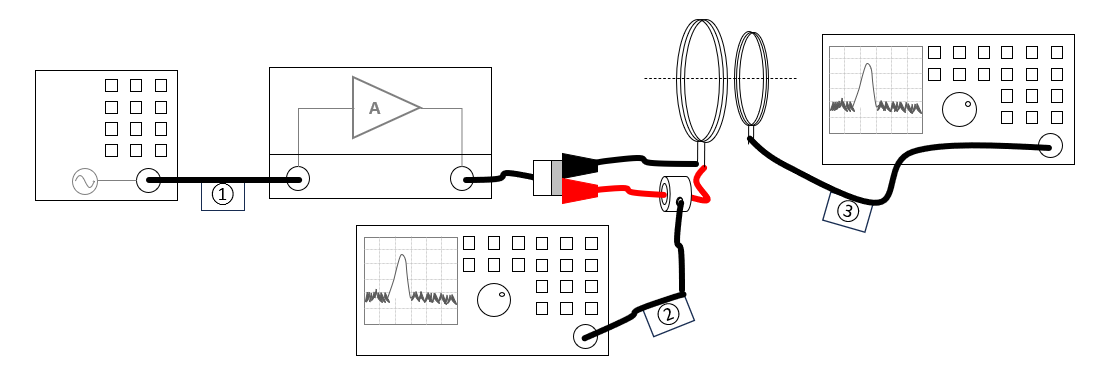
The current flowing through the loop antenna is a one on one relation to the generated magnetic field. For the measurement of the current different measurement methods are available that can be used in combination with RadiMation®. It can be measured using a shunt resistor, or a current sensor. To characterize and validate the generated magnetic field, first a calibration is needed which is using another magnetic field monitoring loop connected to a frequency selective powermeter to verify the result. The result of that calibration can then also be used during the actual substitution test.
Necessary equipment
The following test and measurement devices are needed:
- Signal generator
- Amplifier
- Transmitting loop antenna (accoording the specifications of the used standard)
- Cables
The current flowing through the loop antenna can be measured by one of the following methods, and depending on the used method, the following additional test and measurement devices are also needed:
- Current sensor and powermeter
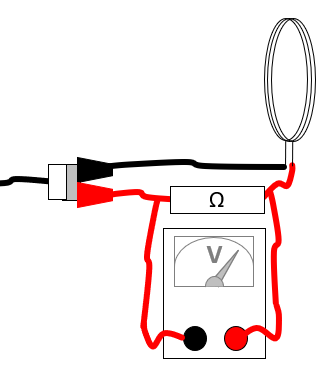
- Resistor and multimeter
- Resistor and oscilloscope
For the calibration of the magnetic field two additional test and measurement devices are also needed:
- Receiving loop antenna (accoording the specifications of the used standard)
- Measurement receiver
Calibration
During the calibration the magnetic field transmitting loop and magnetic field monitoring loop are positioned close to each other, with a specified distance. The current through the magnetic field transmitting loop is then increased until the desired magnetic field level. The magnetic field monitoring loop connected to the spectrum analyser is used to measure the actually generated magnetic field.
Instead of using a current sensor and powermeter, it is also possible to use a shunt resistor and a multimeter, or use the oscilloscope instead of the multimeter
The Magnetic field calibration can be started in RadiMation® by selecting from the menu:
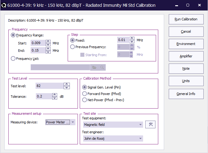
In the Mil Std Calibration dialog, the required settings can be configured. The used standard often specifies most of these settings.
| The start frequency of the calibration. For example 9 kHz |
| The end frequency of the calibration. For example 150 kHz |
| The frequency step that should be used to increment the frequency. For exmaple 10 kHz |
| The percentage of the frequency that should used to increment the freequency. For example 1 % |
| The desired magnetic field testlevel that should be calibrated. For example 82 dBpT |
| The tolerance (specified in dB) that should be used for the accuracy of the regulated testlevel. For exmaple: 0.2 dB |
| Which device is used for the measurement of the current. This can be Current Sensor or Resistor. |
| The device that is used for the measurement of the selected coupling device. This can be Multimeter, Powermeter or Oscilloscope. |
| The name of the testsite that should be used. This testsite should at least have all the required equipment. |
| The name of the engineer who is performing the calibration. |
The Coupling Device and the Measuring Device allow to select the measurement equipment that are used to measure the current through the magnetic field generation loop.
If the Power Meter is selected for the Measuring device, the actually used powermeter should be selected in the testsite as the Sensor powermeter.
The magnetic field generation loop antenna should be selected in the testsite as the Antenna.
The magnetic field monitoring antenna should be selected in the testsite as the Calibration antenna. This antenna device driver should have a Magnetic Field Factor (dBpT/uV) correction file selected as the third correction file in the device driver settings of the antenna device driver. ( also see Magnetic Field Factor correction in Chapter_14 of the manual) The measurement receiver connected to the field monitoring antenna should be selected in the testsite as the Spectrum Analyzer.
When this calibration is started, the signal generator will generate every frequency, and the power level is regulated to the desired magnetic field level as it is measured by the Spectrum Analyzer and the Calibration antenna. At the end of the system calibration a 'Save Calibration As' dialog is shown, which allows to save the result of the calibration to a .CAL calibration file. It is advised to specify a useful location and filename for this magnetic field calibration file.
EUT measurement
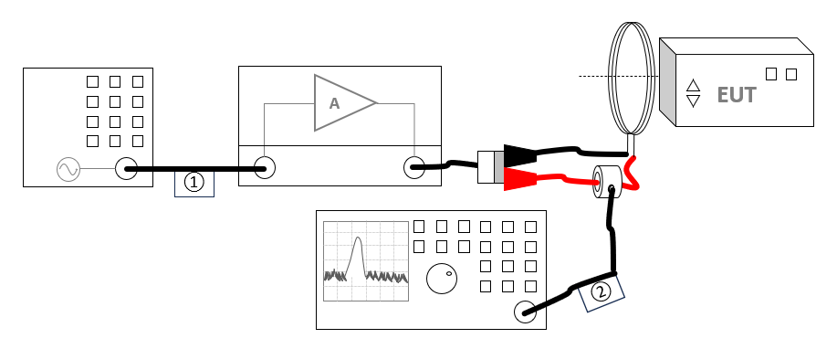
Once the system calibration has been performed, the EUT can be installed and prepared. Also open an EUT file in RadiMation® to store the measurement results of the tests. The equipment configuration that is needed for the actual test is very similar to the calibration setup.
To perform the real magnetic field close proximity test, the earlier created calibration file can be used to generate the requested magnetic field. Just use a Radiated Immunity Multiband test by selecting from the menu:
All the desired test parameters can be set in this configuration window:
... Screenshot of MB immunity test configuration ....
- Start: 0.1 MHz
- End: 1000 MHz
- Previous Frequency: 2 %, which will then use a logarithmic step with a frequency increment that is 2 % of the previous frequency.
- Signal power: 0 dBm, for a generated signal carrier level of 0 dBm.
- Amount of samples: 4, which will perform 4 power measurements on every frequency, and will use the average of those 4 samples, as the result on that frequency.
In the test configuration a Magnetic Field substitution method testlevel can be added. In the Magnetic Field substitution method testlevel configuration the .CAL file can be selected again, and the requested testlevel can be specified. In this configuration dialog, also the levelling method can be selected, which also has the option to regulate on the current flowing through the magnetic field generation loop.
..... Screenshot of Magnetic field Testlevel configuration ....
- Start: 0.1 MHz
- End: 1000 MHz
- Previous Frequency: 2 %, which will then use a logarithmic step with a frequency increment that is 2 % of the previous frequency.
- Signal power: 0 dBm, for a generated signal carrier level of 0 dBm.
- Amount of samples: 4, which will perform 4 power measurements on every frequency, and will use the average of those 4 samples, as the result on that frequency.
The requested test level doesn't need to be the same as the calibrated magnetic field, as RadiMation® will automatically calculate the corresponding current if another testlevel is specified.
When this test is started, the signal generator will be set to every frequency again, the current flowing through the transmitting loop antenna will be regulated to the current that is determined during the calibration, which correlates to the requested magnetic field.
Once the EUT test is finished, the results of this test is stored in the EUT file, and available as one of the performed Tests in the EUT file. Selecting the corresponding test result and pressing on Info will show the test results again.
The magnetic field transmitting loop should be located close to the EUT itself. If the EUT is larger than the illumination area of the transmitting loop, the same test has to be repeated for every 50cm x 50cm area of the EUT, on all sides of the EUT. This can be easily done by repositioning the loop antenna, and starting the same test in RadiMation® again.
Closed loop regulation
Optionally also a Magnetic Flux Density correction file can be selected as the second correction file in the device driver settings of the magnetic field generating loop antenna. The correction file should include a frequency column and a correction column, where the values in the correction column are expressed in 'pT/A'. (also see: Magnetic Flux Density correction file in Chapter_14 of the manual). In the MIL-STD-462, this correction value is specified as 9.5x10^7 pT/A. This Magnetic Flux Density value is used to determine the calculated magnetic field based on the measurement of the current flowing through the magnetic field generation loop antenna.
Conclusion
The RadiMation® Radiated Immunity Mil Std calibration can be used to characterize the generated magnetic field by measuring the current through the transmitting loop, and storing it in a calibration file. The Multiband Radiated Immunity test can then use the calibration file to re-apply the required current (and thus the desired magnetic field) again. This test can then be used to test if the EUT is not influenced by the generated magnetic field.


