File list
This special page shows all uploaded files.
| Date | Name | Thumbnail | Size | Description | Versions |
|---|---|---|---|---|---|
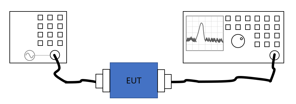
| 12:52, 10 April 2019 | HV-LVAttenuationGainEUTCalibration.png (file) |  |
19 KB | HV-LV Coupling Attenuation measurement, using the Attenuation/Gain EUT calibration, using a setup with a signal generator and a spectrum analyzer. | 1 |
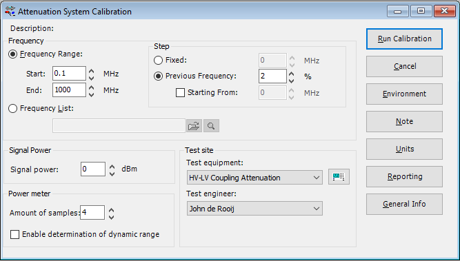
| 13:06, 10 April 2019 | HV-LVCouplingAttenuationSystemCalibrationTSF.png (file) |  |
18 KB | Screenshot of the TSF configuration dialog of the Attenuation/Gain System calibration, where it is configured to perform a measurement of the HV-LV Coupling attenuation. | 1 |
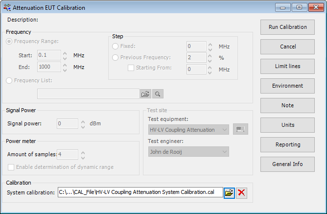
| 14:04, 10 April 2019 | HV-LVCouplingAttenuationEUTCalibrationTSF.png (file) |  |
23 KB | Screenshot of the TSF configuration dialog of the Attenuation/Gain EUT calibration, where it is configured to perform a measurement of the HV-LV Coupling attenuation. | 1 |
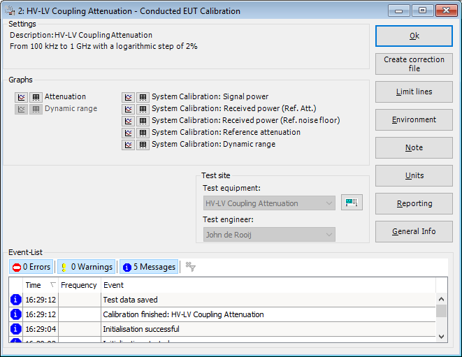
| 14:46, 10 April 2019 | HV-LVAttenuationGainEUTCalibrationResult.png (file) |  |
25 KB | The window that is shown to present the result of the Attenuation/Gain EUT calibration. In this example specifically for the HV-LV Attenuation measurement. | 1 |
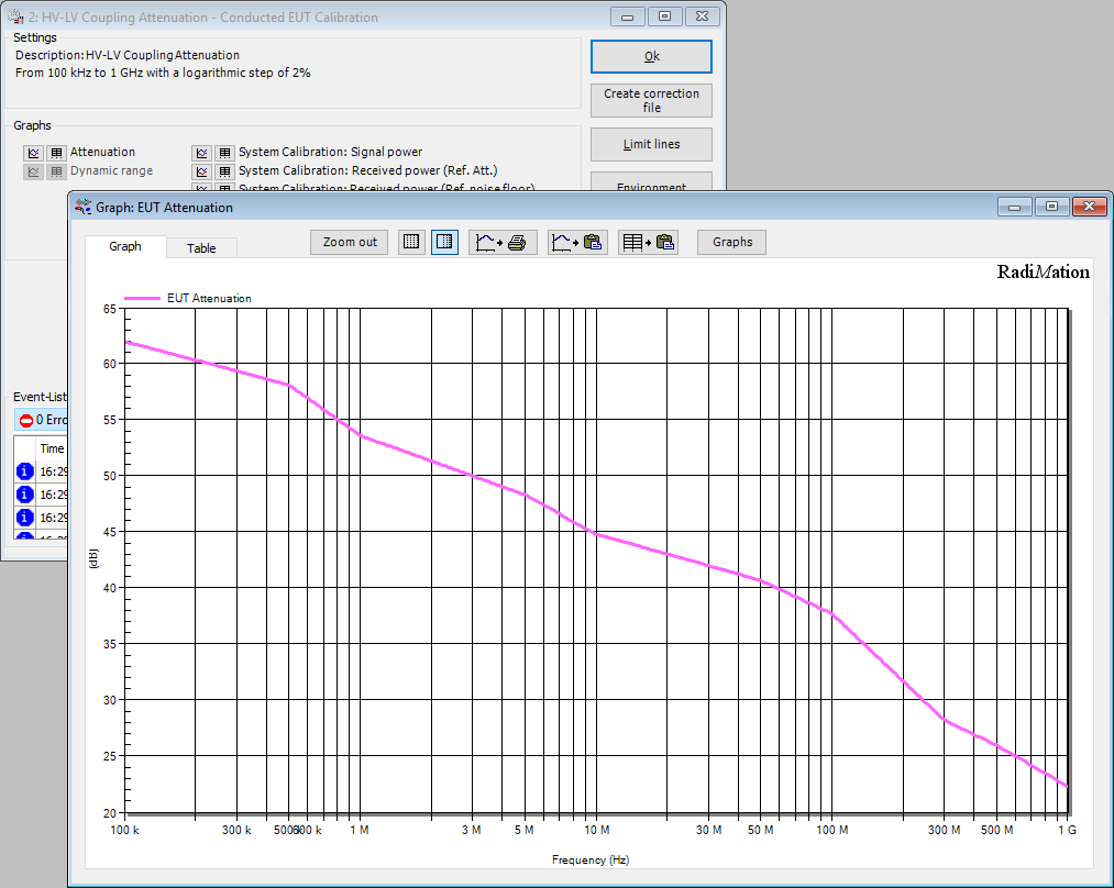
| 14:49, 10 April 2019 | HV-LVAttenuationGainEUTCalibrationResultGraph.png (file) |  |
67 KB | The window that is shown to present the result of the Attenuation/Gain EUT calibration, also showing the EUT Attenuation graph. In this example specifically for the HV-LV Attenuation measurement. | 1 |
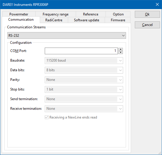
| 13:51, 3 January 2020 | RS-232 DeviceStream Configuration.png (file) |  |
13 KB | Screenshot of the RS-232 DeviceStream configuration dialog Category:Screenshot | 1 |
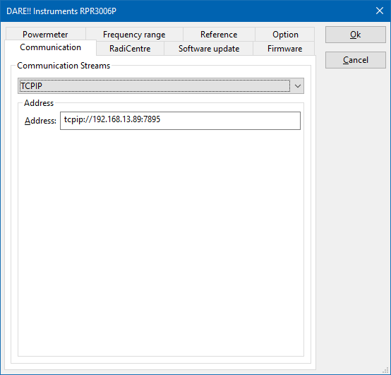
| 13:51, 3 January 2020 | TCPIP DeviceStream Configuration.png (file) |  |
10 KB | Screenshot of the TCPIP DeviceStream configuration dialog Category:Screenshot | 1 |
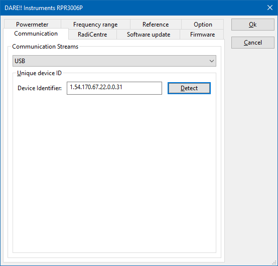
| 13:52, 3 January 2020 | USB DeviceStream Configuration.png (file) |  |
10 KB | Screenshot of the USB DeviceStream configuration dialog Category:Screenshot | 1 |
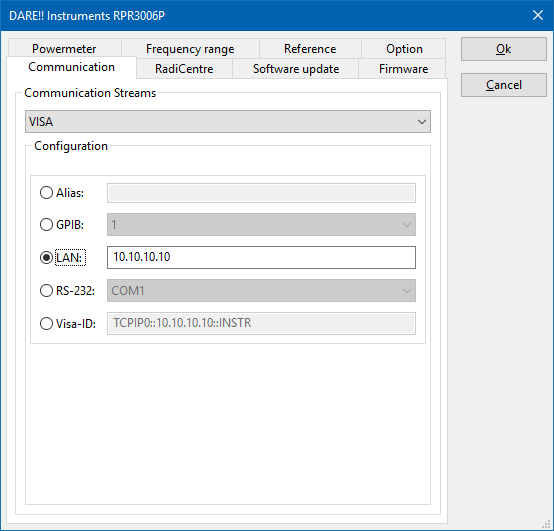
| 13:52, 3 January 2020 | VISA DeviceStream Configuration.png (file) |  |
14 KB | Screenshot of the VISA DeviceStream configuration dialog Category:Screenshot | 1 |
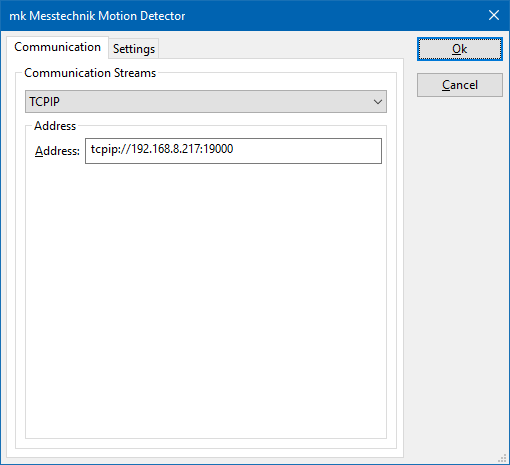
| 13:14, 14 May 2020 | MkMesstechnikMotionCommunication.png (file) |  |
6 KB | The communication settings dialog, to configure the communication with the mk Messtechnik Motion detection server. | 1 |
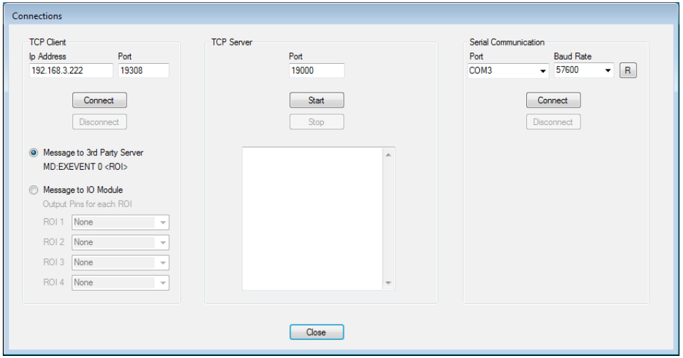
| 13:15, 14 May 2020 | MkMesstechnikMotionServerSettings.png (file) |  |
49 KB | The configuration settings on the server software of the mk Messtechnik motion detection software. This is thus a dialog of the software of mk Messtechnik. This is not a dialog that is part of our {{RadiMation}} software. | 1 |
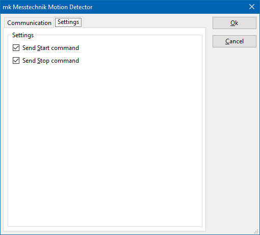
| 13:17, 14 May 2020 | MkMesstechnikMotionSettings.png (file) |  |
6 KB | A screenshot of the mk Messtechnik motion detection device driver, where the settings of the device driver can be configured. Also see: mk Messtechnik Motion Detector Category:Screenshot | 1 |
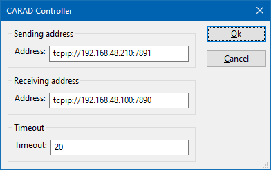
| 14:20, 5 June 2020 | CARADControllerAddressSettings.png (file) |  |
5 KB | The configuration dialog of the CARAD device driver, that shows the address that can be configured for the communication settings. Category:Screenshot | 1 |
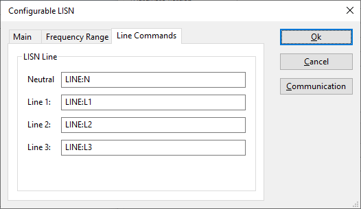
| 10:27, 10 June 2020 | ConfigurableLISNLineCommandsTab.png (file) |  |
7 KB | The Line Commands tab of the Configurable LISN device driver Category:Screenshot | 1 |
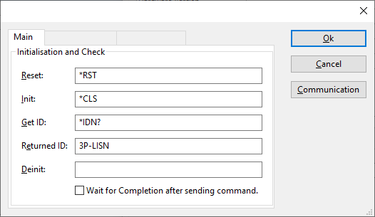
| 10:52, 10 June 2020 | ConfigurableLISNMainTab.png (file) |  |
9 KB | 2 | |
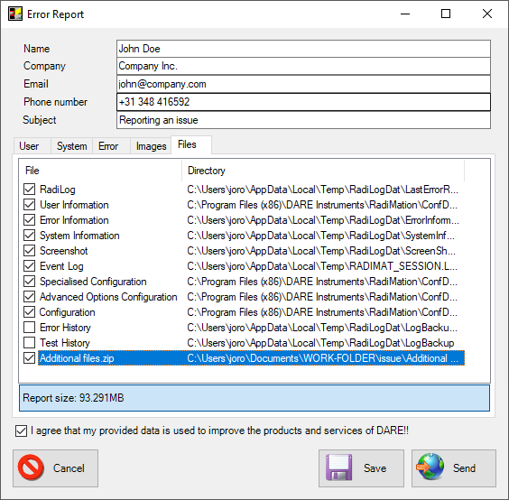
| 07:35, 12 June 2020 | ErrorReportFilesTab.png (file) |  |
35 KB | Shows the Error Report dialog, where the {{ScreenElement|Files}} tab is shown with an 'Additional Files.zip'. Category:Screenshot | 1 |
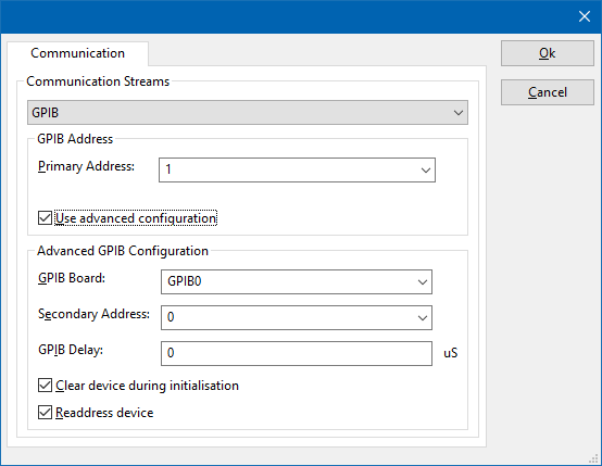
| 11:29, 12 June 2020 | GPIB DeviceStream Configuration.png (file) |  |
14 KB | Removed the title, and the other tabs that are not relevant. | 2 |
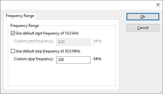
| 11:53, 12 June 2020 | ConfigurableFrequencyRangeTab.png (file) |  |
9 KB | * Removed the Communication button * Removed the other tabs Both are not relevant for the explanation of the settings on this tab. | 3 |
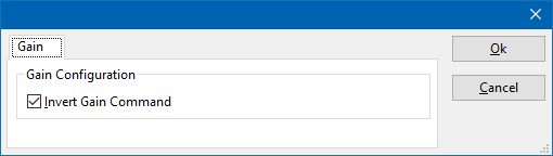
| 07:41, 9 July 2020 | AmplifierResearchGainTab.png (file) |  |
3 KB | Shows the 'Gain' tab of the Amplifier Research amplifier device drivers. Category:Screenshot | 1 |
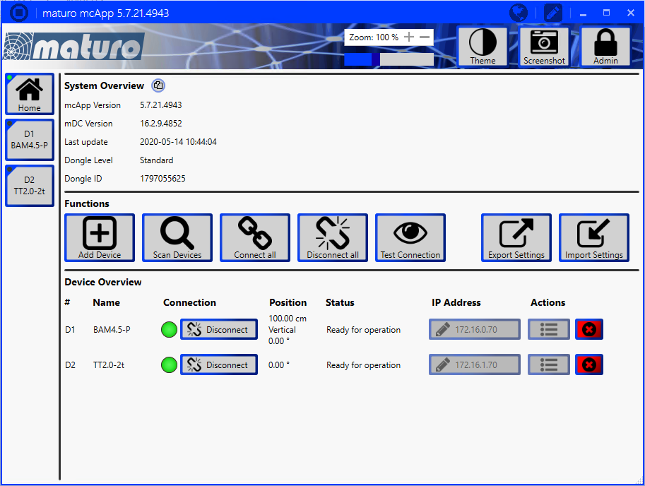
| 12:47, 27 July 2020 | Maturo mcApp Home.png (file) |  |
145 KB | naturo mcApp software, showing the 'Home' page. Category:Screenshot | 1 |
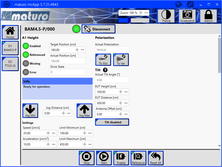
| 12:47, 27 July 2020 | Maturo mcApp AntennaTower.png (file) |  |
148 KB | naturo mcApp software, showing the page of an antenna tower Category:Screenshot | 1 |
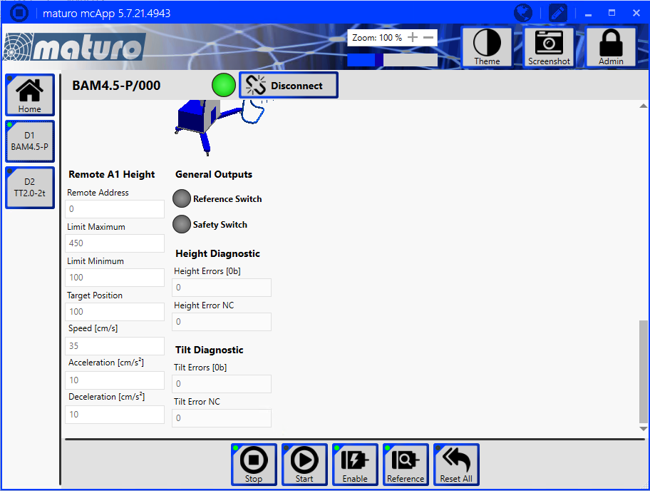
| 12:48, 27 July 2020 | Maturo mcApp AntennaTower RemoteAddress.png (file) |  |
123 KB | naturo mcApp software, showing the page of an antenna tower, which shows the 'Remote Address' field. Category:Screenshot | 1 |
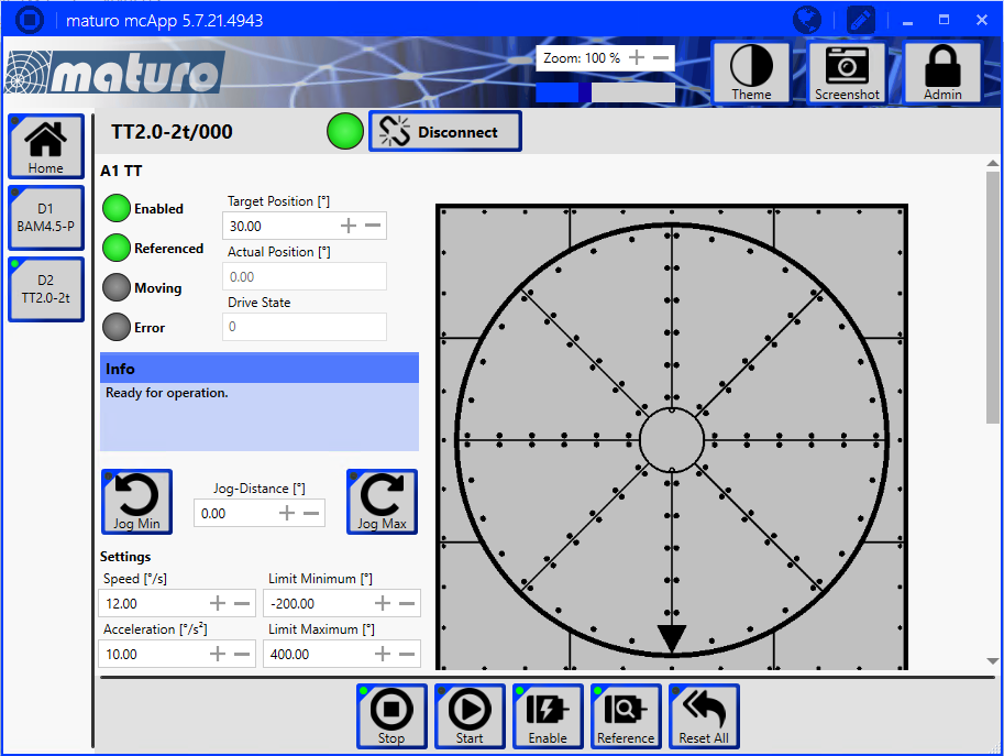
| 12:48, 27 July 2020 | Maturo mcApp Turntable.png (file) |  |
160 KB | naturo mcApp software, showing the page of a turntable Category:Screenshot | 1 |
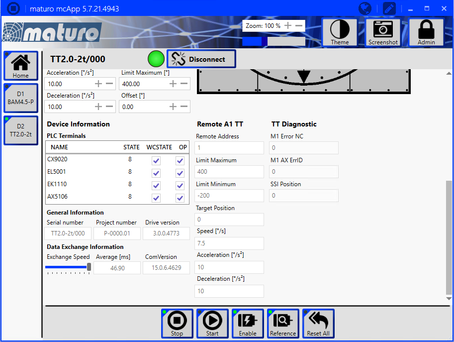
| 12:48, 27 July 2020 | Maturo mcApp Turntable RemoteAddress.png (file) |  |
137 KB | naturo mcApp software, showing the page of a turntable, where the 'Remote Address' field is also visible. Category:Screenshot | 1 |
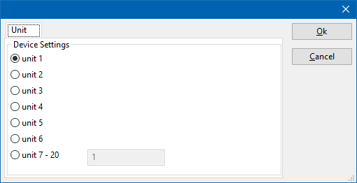
| 13:08, 27 July 2020 | DeviceDriverUnitSelection.png (file) |  |
7 KB | Shows a device driver configuration dialog to select the unit. 'Unit 1' is the selected unit. | 1 |
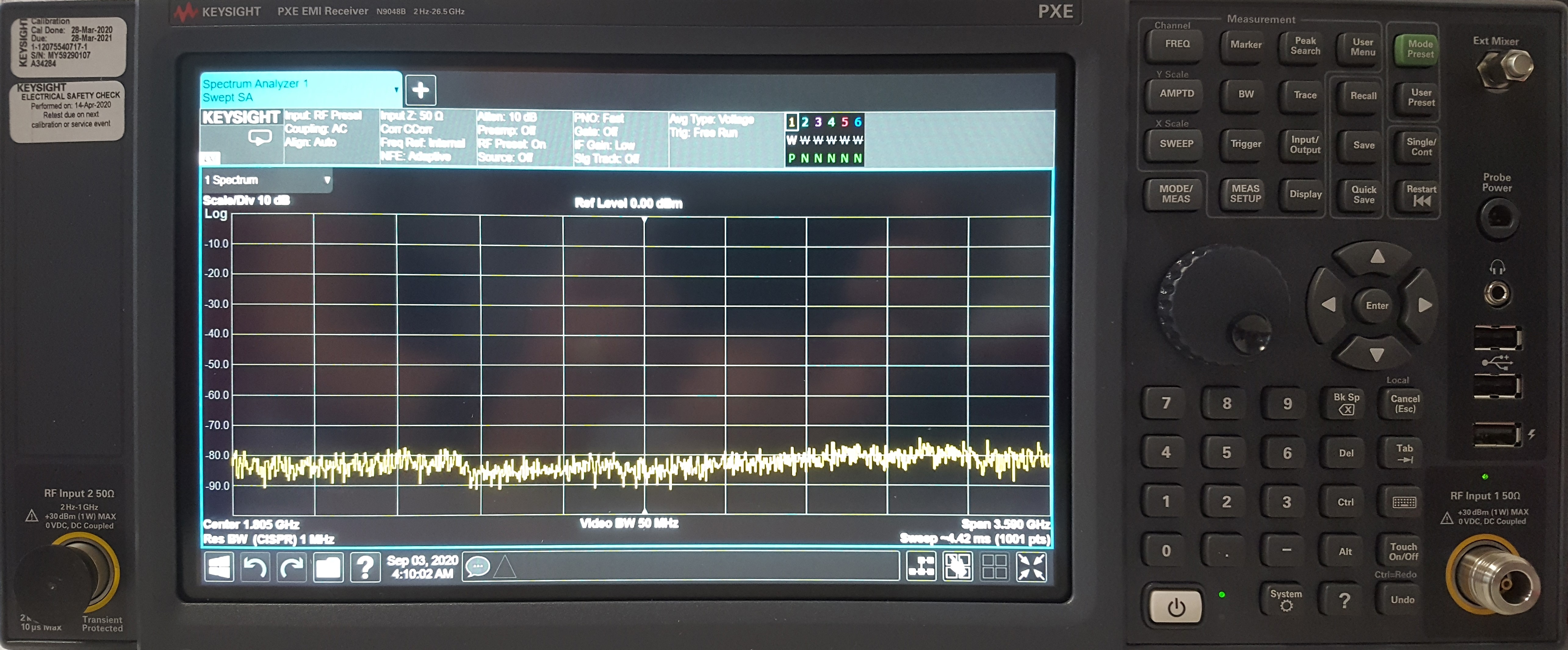
| 19:34, 3 September 2020 | Keysight Technologies N9048B front.jpg (file) |  |
1.69 MB | Front of the Keysight Technologies N9048B | 1 |
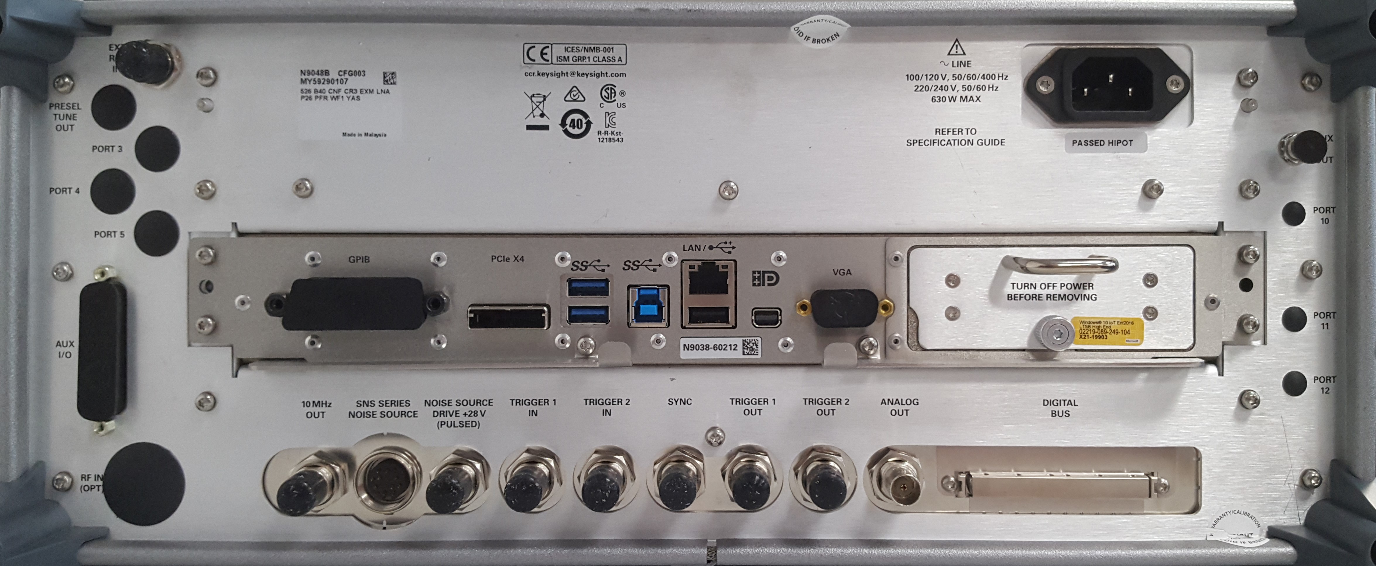
| 19:36, 3 September 2020 | Keysight Technologies N9048B back.jpg (file) |  |
1.38 MB | Back of the Keysight Technologies N9048B | 1 |
| 08:20, 13 October 2020 | RSUPP400PossibleConfiguration.png (file) |  |
135 KB | A possible configuration of the software settings of the Rohde & Schwarz UPP400 | 1 |
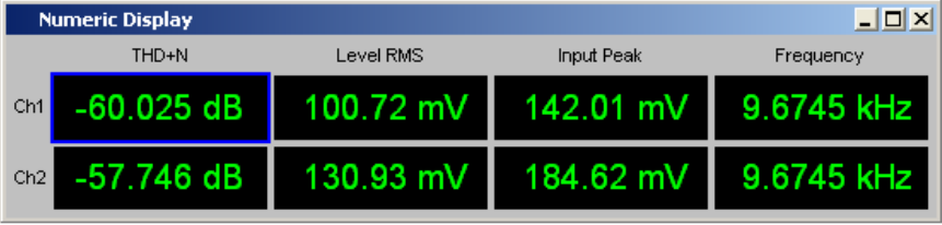
| 08:21, 13 October 2020 | RSUPP400PossibleNumericDisplay.png (file) | 42 KB | An example of how the Numeric Display could be shown in the Rohde & Schwarz UPP400 software. | 1 | |
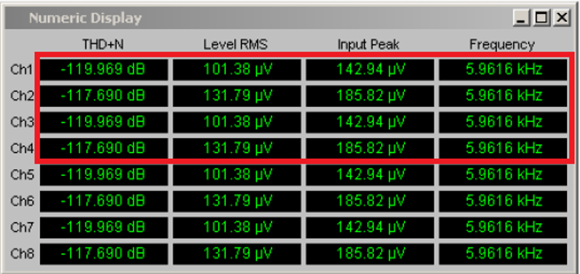
| 08:23, 13 October 2020 | RSUPP400RetrievableFieldsFromNumericDisplay.png (file) |  |
121 KB | A screenshot of the Rohde & Schwarz UPP400 Numeric Display, also identifying which fields and values can be retrieved by the {{RadiMation}} device driver for the Rohde & Schwarz UPP400. | 1 |
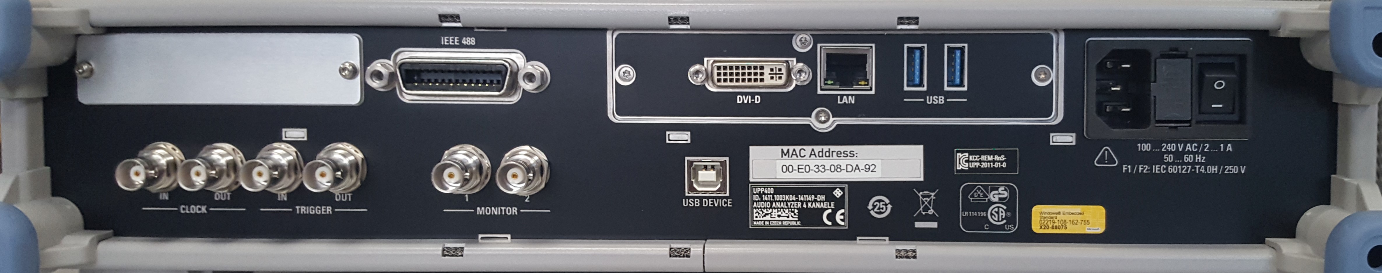
| 09:21, 13 October 2020 | Rohde & Schwarz UPP400 back.jpg (file) | 693 KB | Back of the Rohde & Schwarz UPP400 | 1 | |
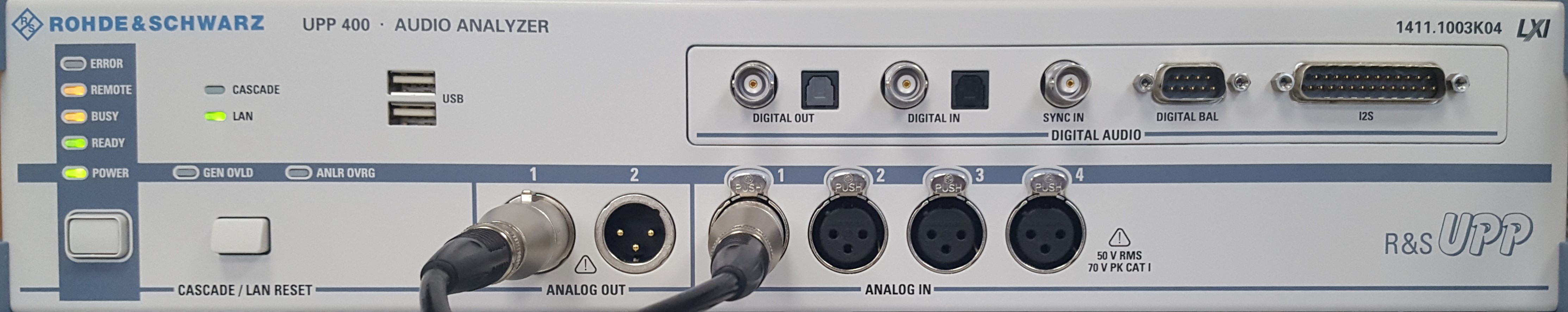
| 09:21, 13 October 2020 | Rohde & Schwarz UPP400 front.jpg (file) | 609 KB | Front of the Rohde & Schwarz UPP400 | 1 | |
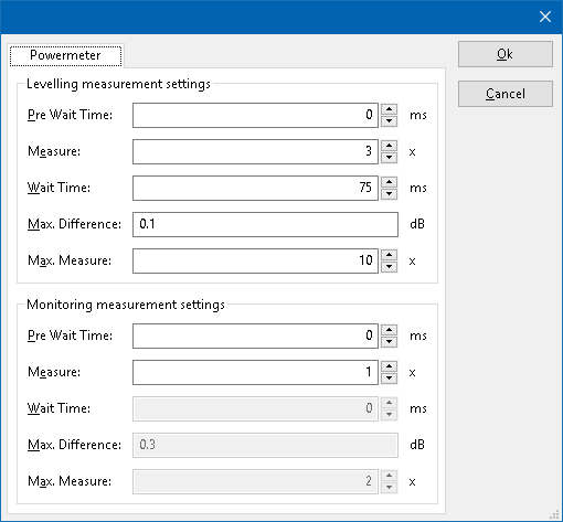
| 14:20, 13 October 2020 | PowerMeterPanel.png (file) |  |
9 KB | 2 | |
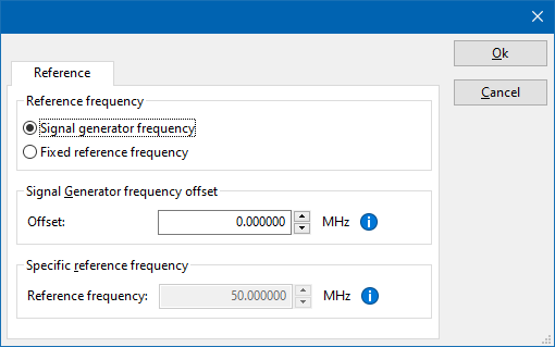
| 05:57, 14 October 2020 | DeviceDriverReferenceTab.png (file) |  |
8 KB | Shows the 'Reference' tab of a powermeter device driver. Also see: DeviceDriverReferenceTab. | 1 |
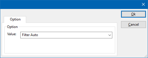
| 06:23, 14 October 2020 | DeviceDriverOptionTab.png (file) |  |
3 KB | Screenshot of the Option tab of a RadiPower device driver. | 1 |
| 10:07, 2 December 2020 | DriversExeStartPage.PNG (file) |  |
41 KB | 3 | |
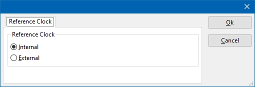
| 13:44, 30 December 2020 | DeviceDriverReferenceClockTab.png (file) |  |
3 KB | Shows the 'Reference Clock' tab from the device driver. | 1 |
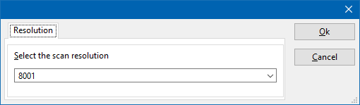
| 13:51, 30 December 2020 | DeviceDriverResolutionTab.png (file) |  |
3 KB | Shows the resolution tab of the device driver configuration window. | 1 |
| 11:53, 12 January 2021 | MultibandGraphInReport.jpg (file) |  |
31 KB | Reverted to version as of 08:50, 26 June 2007 (UTC) | 3 |
| 20:42, 28 February 2021 | Download-button.png (file) | 1 KB | Upload button to reflect the Raditeq style. | 3 | |
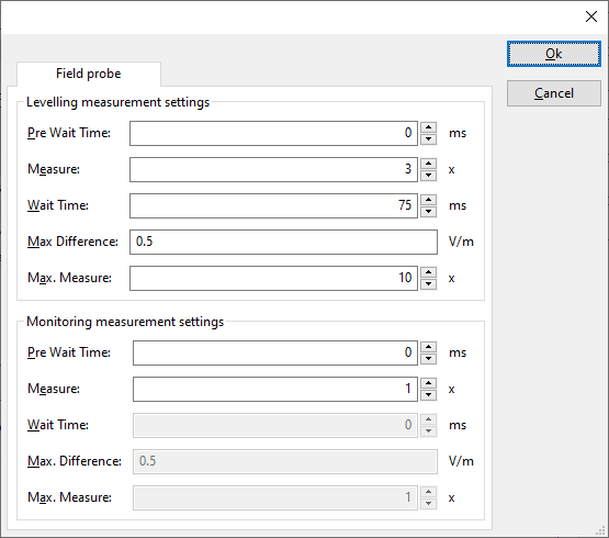
| 10:40, 8 March 2021 | FieldProbePanel.png (file) |  |
12 KB | Shows the settings of the field probe measurement settings in the device driver configuration of the fieldprobe. | 1 |
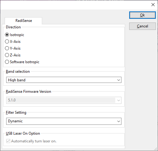
| 12:48, 8 March 2021 | DeviceDriverRadiSense2000Tab.png (file) |  |
6 KB | Shows the RadiSense tab of the RadiSense 2000 advanced device driver configuration dialog | 1 |
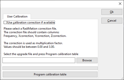
| 12:54, 8 March 2021 | DeviceDriverRadiSenseUserCalibrationTab.png (file) |  |
10 KB | Shows the configuration panel of the 'User Calibration' of the RadiSense advanced device driverconfiguration | 1 |
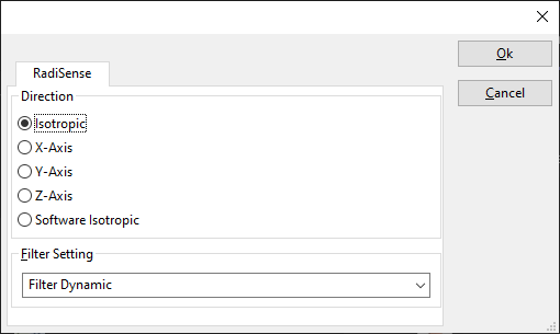
| 13:13, 8 March 2021 | DeviceDriverRadiSenseTab.png (file) |  |
10 KB | Shows the configuration panel of the RadiSense, in the advanced device driver configuration. | 1 |
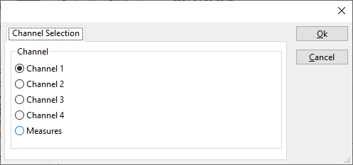
| 08:10, 20 April 2021 | DeviceDriverLeCroyChannelSelectionTab.png (file) |  |
5 KB | Shows the Channel selection tab of the LeCroy oscilloscope drivers. | 1 |
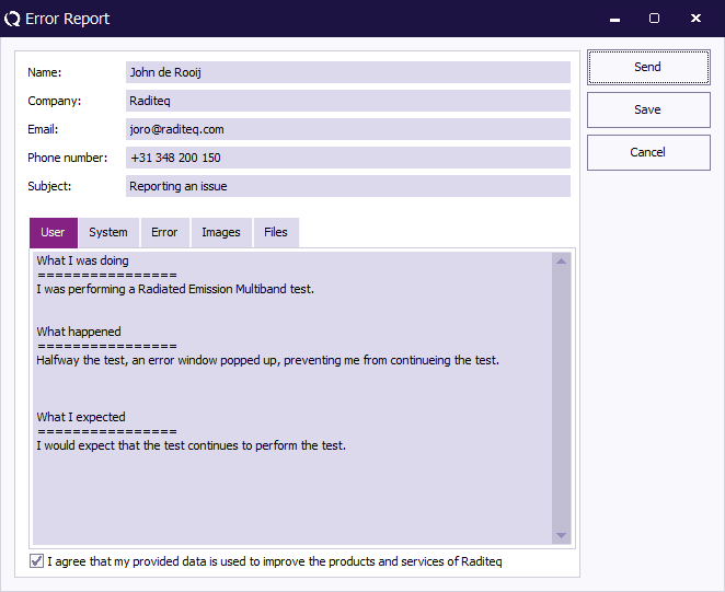
| 14:05, 5 May 2021 | ReportErrorWindow.png (file) |  |
19 KB | 5 | |
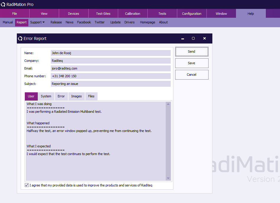
| 14:09, 5 May 2021 | ManualReportMenu.png (file) |  |
37 KB | 3 | |
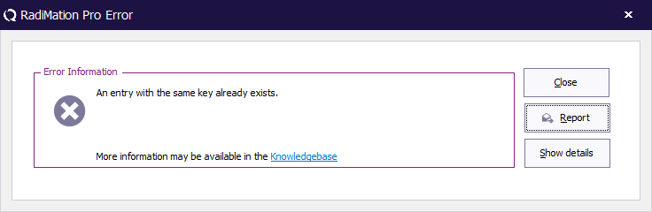
| 14:13, 5 May 2021 | ErrorPopupWindow.png (file) |  |
8 KB | 4 | |
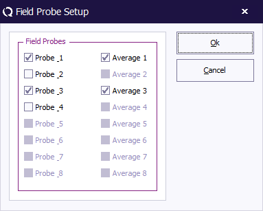
| 14:35, 19 May 2021 | OnePointCalibrationFieldProbeSetup.png (file) |  |
7 KB | Shows the Field Probe setup dialog from the Radiated Immunity 1 point calibration. It shows that only probe 1 and probe 3 are selected, and that both of them are also selected to be included in the average. Category:Screenshot | 1 |
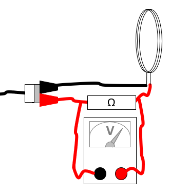
| 14:33, 28 January 2022 | MagneticFieldShuntResistor.png (file) |  |
14 KB | Equipment connections for measuring the current through a magnetic loop antenna using a shunt resistor. | 1 |