RadiMation Application Note 101: Difference between revisions
| Line 35: | Line 35: | ||
{{Note|<i> | {{Note|<i> | ||
Additional information during this step: [[Chapter_2#Test_equipment_list_configuration | http://wiki.dare.nl/wiki/index.php/Chapter_2#Test_equipment_list_configuration]] | |||
</i>}} | </i>}} | ||
Revision as of 14:13, 28 July 2014
Optimize Height and Optimize Angle[edit]
This Application Note will explain how the Optimize Height and Optimize Angle settings can be configured in RadiMation. It is used when performing the Radiated Emission measurements.
Table of Contents[edit]
- Introduction
- How to perform a basic Radiated Emission test?
- How to use the Continuous Measure method?
- How to use Optimize Angle?
Introduction[edit]
In this application note detailed explanation of the specific functionality ‘Optimize Angle’ and ‘Optimize Height’ is described. The main purpose it to convey how it can be used during a test or to further optimize the performance of a test. The objective is to present the measurement tips and procedures to be used in practice. When applying this application note in practice we advise to use at least RadiMation 2013.x or 2014.x versions. A valid Software Protection Key with the Radiated Emission module installed is required to perform the tests. Expected end-user skill level is rated beginner or novice.
How to perform a basic Radiated Emission test?[edit]
We will describe briefly how to start a basic Radiated Emission test.
Step 1: Adding drivers[edit]
Here will be explained how to add (virtual) device drivers. Select from the RadiMation® main Menu:
-
 Configuration
-
 Configuration
-
 Device Drivers
-
-
-
Select the desired Device Driver Type from the drop-down menu and create the new driver.
| Note: |
For additional information during this step check: http://wiki.dare.nl/wiki/index.php/Chapter_2#Device_driver_configuration |
Step 2: Create Test-site[edit]
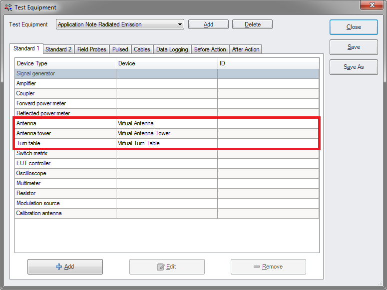
Configure also a new Test Equipment for the Radiated Emission test.
-
 Test-Sites
-
 Configure...
-
 Add
Add
-
-
-
Enter a new name and click Ok. The minimum of device types we need for to be added to this equipment is: Antenna, Turn Table, Spectrum Analyser or Scanning Receiver. When finished click Save and click Close.
| Note: |
Additional information during this step: http://wiki.dare.nl/wiki/index.php/Chapter_2#Test_equipment_list_configuration |
Step 3: Create EUT[edit]
Create a new EUT for this Application Note. Choose from the RadiMation main Menu:
-
 File
File
-
 New
New
-
 EUT
EUT
-
-
-
Step 4: Start new test[edit]
Enter a new name and click Save. Do not close the EUT window after it is created. Start a new Radiated Emission test of the type Multiband. Open from the RadiMation main Menu:
-
 Tests
Tests
-
 Radiated Emission
-
 Multiband
-
 New
New
-
-
-
-
Step 5: Configure TSF[edit]
Select from the opened Test Setup File (TSF) window the desired Frequency Range to be measured.
Select the appropriate Test Equipment created during Step 2 from the drop down menu.
How to use the Continuous Measure method?[edit]
- Write
- Max-hold
How to use Optimize Angle?[edit]
- Configuration in TSF and after pre-measurement
- Interpret of the Angle polar plot graph


