Difference between revisions of "RadiMation Application Note 114"
(→How to measure data from the EUT using the Configurable AD Convertor device driver) |
(→Specify the communication type) |
||
| Line 97: | Line 97: | ||
===Specify the communication type=== | ===Specify the communication type=== | ||
| − | The correct settings for the communication with the measurement device (which is the EUT in this example) must also still be configured. The Configurable AD Convertor supports several communication types, which can be used to communicate with the measurement device. Click on the {{ScreenElement|Communication}} button, to open the configuration dialog to specify the actual details of the medium to use for the communication. Depending on the connection that is used, select the correct {{ScreenElement|Communication Stream}}, and configure the parameters correspondingly to communication settings that are used by device. Different {{ScreenElement|Communication Stream}}s are available, which are described in more detail in the [[Chapter_15#Communication_settings|Communication settings]] section of [[Chapter 15]]. | + | The correct settings for the communication with the measurement device (which is the actual EUT in this example) must also still be configured. The Configurable AD Convertor supports several communication types, which can be used to communicate with the measurement device. Click on the {{ScreenElement|Communication}} button, to open the configuration dialog to specify the actual details of the medium to use for the communication. Depending on the connection that is used, select the correct {{ScreenElement|Communication Stream}}, and configure the parameters correspondingly to communication settings that are used by device. Different {{ScreenElement|Communication Stream}}s are available, which are described in more detail in the [[Chapter_15#Communication_settings|Communication settings]] section of [[Chapter 15]]. |
In this example the {{ScreenElement|RS-232}} stream is selected, and the {{ScreenElement|COM Port}} is set to COM3 to allow communication with the central heating boiler. | In this example the {{ScreenElement|RS-232}} stream is selected, and the {{ScreenElement|COM Port}} is set to COM3 to allow communication with the central heating boiler. | ||
Revision as of 18:32, 30 January 2023
How to measure data from the EUT using the Configurable AD Convertor device driver
This Application Note explains how the Configurable AD Convertor can be used to monitor an EUT. With the Configurable AD convertor, any type of signal can be measured, monitored and plotted within RadiMation® during an immunity test.
Let's assume that the EUT is a central heating boiler, and that the temperature of the water inside the boiler should be measured and monitored. The central heating boiler has a serial port (which is connected to COM3 on the testing PC), and if the command: "TEMP?" is transmitted, the microcontroller on the boiler will respond with: "Temp: 46.5".
The configuration in RadiMation® can be separated in two steps:
- Configure the Configurable AD Convertor device driver to retrieve the value from the measurement device.
- Plot the measured value during an immunity test using the correct unit.
Configuring the Configurable AD convertor
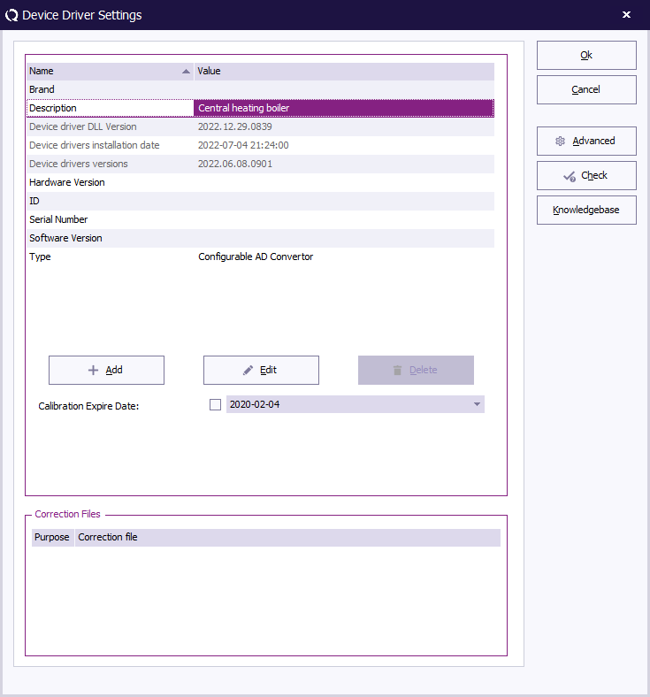
First create a new Configurable AD Convertor device driver. It is best to give this new device driver a descriptive description to identify it clearly for the task that it is used for. In this example 'Central heating boiler' would be a suitable name.
After the device driver is created, open the Advanced settings window of the new device driver, which allows to further specialise how the driver should communicate with the actual device.
Configure the commands for the initialisation of the device
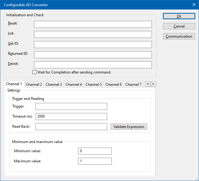
The Configurable AD Convertor device driver has several boxes, in which the remote programming commands can be specified, which should be transmitted to the measurement device on defined moments.
| The reset code that needs to be transmitted to device. When left blank, no command will be transmitted. |
| The command that is transmitted to initialise the configured device. When left blank, no command will be transmitted. |
| The query-command that is transmitted to retrieve the ID of the device. This is used to check if the device is connected. A commonly used SCPI command is: '*IDN?'. When left blank, no command will be transmitted. |
| If the checkbox is ticked, RadiMation® will wait for all the commands to complete, before it continues. This is achieved by also transmitting the SCPI query-command '*OPC?' to the device, and waiting for the response. |
Configure the measurement and interpretation of the measured value
AD convertors can have multiple channels from which values can be read. The Configurable AD Convertor device driver is able to retrieve the values from up to 50 different channels from the measurement device. For each AD channel, an individual query-command can be specified, specific for the measurement value that should be retrieved.
The configuration of a single channel can be configured on one of the specific Channel <nr> tabs.
| The trigger query-command can be specified to trigger and request a new measurement value from the device. A commonly used SCPI query-command is: 'READ?'. |
| The timeout (specified in milliseconds) that should be used to read the response from the device. If no valid response is received within the timeout it is assumed that no value is read. |
| Different measurement devices will return the measured value in different formatting. The configurable AD convertor is able to determine the numeric value of the measurement device response by using regular expressions. The text in the Read Back box, is used as the regular expressions to determine the numeric value in the response of the measurement device.
The regular expression for finding the first numeric value (including fractional and scientific notation) in a text is: ([+-]?[0-9]*\.?[0-9]+([eE][+-]?[0-9]+)?) The part of the regular expression that is contained in the round brackets, is retrieved as the measurement value and converted to a numeric value. For more possibilities see the Read Back examples section. |
The minimum and maximum measurable value of the measurement device can be specified to correctly scale the measured value. This will also be used to re-calculate the retrieved measurement value to another value with another unit.
| The lowest value of the channel that can be measured with the controlled measurement device. The value must be the same as filled in the EUT window. It normally is the best to configure this value to be 0. |
| The highest value of the channel that can be measured with the controlled measurement device. The value must be the same as filled in the EUT window. It normally is the best to configure this value to be 1. |
Read Back examples
| Received information | Regular expression | Determined measurement value | Note |
|---|---|---|---|
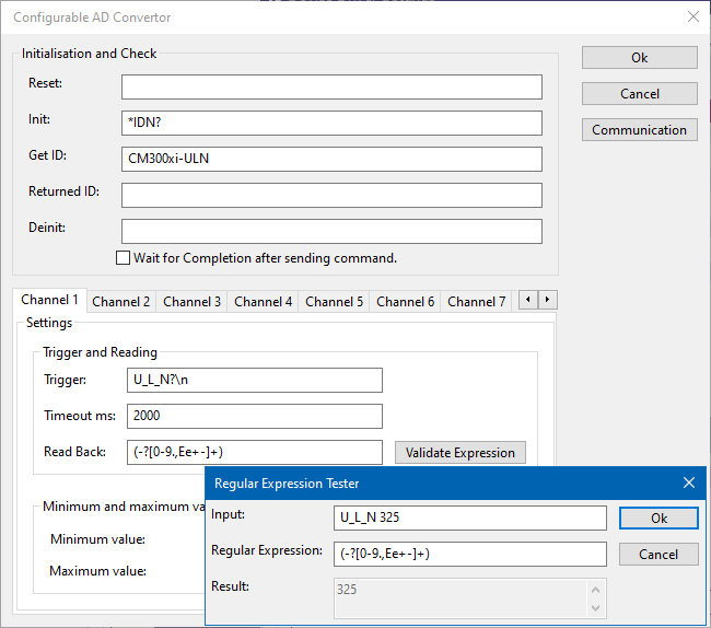
| U_L_N 325 | (-?[0-9.,Ee-]+) | 325 | Takes the first number. |
| I_L1;12.34 | ;(-?[0-9.,Ee-]+) | 12.34 | Takes the first number after ";". |
| THD_U_L1;;14,5 | ;;(-?[0-9.,Ee-]+) | 14.5 | Takes the first number after ";;". |
| AC_FREQ;Channel1;1.23E3 | ;.*;(-?[0-9.,Ee-]+) | 1230 | Takes the first number after the appearance of a second ";". |
The correctness of the regular expression can be tested, verified and improved by using the Validate Expression tool within the configurable device driver.
In the Regular Expression Tester, the following fields are available to verify the regular expression:
| Any text that is expected to be returned by the device. |
| The Regular expression that is being tested. This regular expression will be used to use the text from Input and convert it into a numerical value. |
| The numerical value that is determined by the device driver using the Regular Expression on the Input. |
Specify the communication type
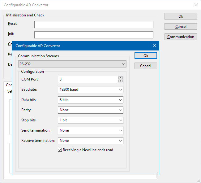
The correct settings for the communication with the measurement device (which is the actual EUT in this example) must also still be configured. The Configurable AD Convertor supports several communication types, which can be used to communicate with the measurement device. Click on the Communication button, to open the configuration dialog to specify the actual details of the medium to use for the communication. Depending on the connection that is used, select the correct Communication Stream, and configure the parameters correspondingly to communication settings that are used by device. Different Communication Streams are available, which are described in more detail in the Communication settings section of Chapter 15.
In this example the RS-232 stream is selected, and the COM Port is set to COM3 to allow communication with the central heating boiler.
After this last configuration, the device driver is configured correctly and all configuration windows can be closed.
Plot the measured value during an immunity test using the correct unit
Create a new monitoring input channel
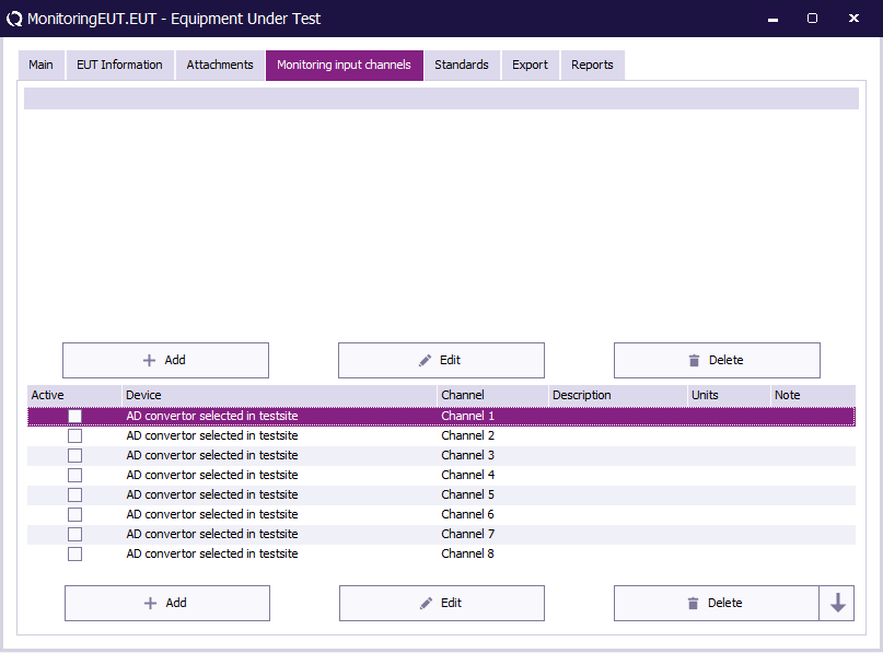
- The monitoring functionality is applied to the EUT. Therefor we first need to have an EUT file opened.
- In the opened EUT file, we can select the Monitoring input channels tab.
- Double click an existing input channel or add a new input by using the add button.
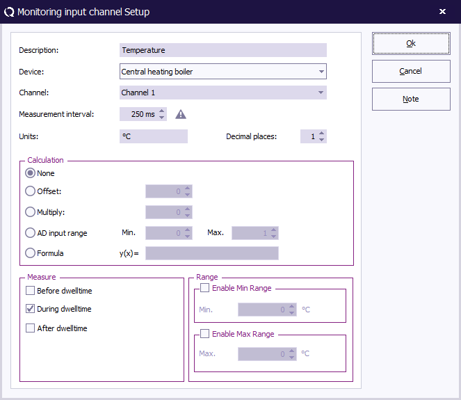
- A new window will open to configure the monitoring input channel.
Configure a monitoring input channel
- At the device menu, the newly configured AD convertor can be selected.
- The selected AD channel must be selected.
- The Unit type can be specified as text.
- With Calculation, the raw value from the AD convertor can be modified to match the preferred unit. More information can be found here.
- The Monitoring Input channel description will be shown in the graph title.
- After pressing Ok to save the configurations, ensure that the configured monitoring channel is marked as Active in the monitoring input channels list.
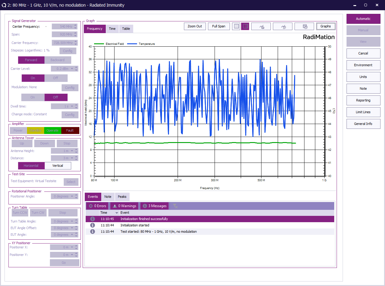
Running a test
When an immunity test is performed, RadiMation will also measure the value from the measurement device and it will plot the line(s) of the activated monitoring input channel(s). By switching to the Table tab, the measurement values will be shown in a tabular style.
