How to measure amplifier harmonics using RadiMation
This application note explains how RadiMation® can be used to perform accurate measurement of the harmonics that are generated by an amplifier.
The measurement of the harmonics is often needed to ensure that the used amplifier in the amplifier setup is not generating too much power on multiples of the carrier frequency.
The first harmonic is the same as the generated CW signal which is the input signal for the amplifier. The second harmonic is present at 2x the CW frequency. The third harmonic is present at 3x the CW frequency, and so on.
As the harmonics are thus present on higher frequencies than the CW signal, all the equipment that is connected to the output of the amplifier up to and including the used spectrum analyser should be able to be used on those higher frequencies. For an amplifier of 80 MHz - 1000 MHz, measuring up to the 6th harmonic, it is thus necessary that the measurement equipment is usable up to 6 GHz.
Overview
There are two possible setups of the used equipment to measure amplifier harmonics.
- Measure the initial power on the first harmonic and the additional harmonics with a spectrum analyser.
- Measure the initial power with a broadband power meter and measure the harmonics with a spectrum analyser.
A schema of the test setup:
File:Harmonics schematic.png
For the 'Load' an actual high power RF load can be used, or it can also be the normally to be used intended equipment, like for example the antenna in an anechoic chamber.
Configuring the testsite
Using a spectrum analyser
To use only the spectrum analyser we need to configure the the Forward power meter to be the spectrum analyser device driver in the testsite.
Keep in mind to not select any device for the sensor power meter on the second tab.
File:Harmonics Configure Spectrum analyser as power meter.PNG
Using a broadband powermeter and a spectrum analyser
When using the powermeter to setup the required testlevel and a spectrum analyser to measure the harmonics we need to setup the forward power meter to the power meter and on the devices 2 tab we select the spectrum analyser.
File:Harmonics Configure Broadband power meter.PNG
File:Harmonics Configure Spectrum Analyser as Sensor Power meter.PNG
Configuring the calibration
To start the harmonics calibration first, open an EUT file and select from the menu:
-
 Calibration
- EUT Calibration
- Harmonics
The configuration window for the harmonics calibration will be shown, which allows to configure all the parameters.
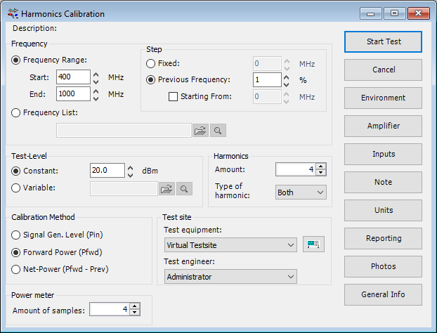
 Description Description
|
The name of the selected TSF file.
|
| Frequency Range
|
Sets the frequency specification to a frequency range.
|
| Start
|
Sets start frequency.
|
| End
|
Sets end frequency.
|
| Step Fixed
|
Sets a fixed step size from start to end frequency.
|
| Step Previous Frequency
|
Sets a logarithmic step size from start to stop frequency
|
| Starting From
|
Sets the start frequency for a logarithmic step from which the actual measurement frequencies will be calculated. the starting from frequency should be lower then the actual start frequency. The test will start at the first calculated frequency that is equal or higher then the specified start frequency.
|
| Frequency list
|
With frequency list the operator can select a frequency list file by browsing to the file location. The frequencies inside the frequency list file will be measured.
|
| Constant
|
The test level can be set to a constant level to which the power should be regulated.
|
| Variable
|
A .COR file can also be used. This can be the same file as for the Frequency List.
|
| Amount
|
The number of harmonics that should be measured.
|
| Type of harmonic
|
If only the even, odd or both (even and odd) harmonics should be measured.
|
| Calibration method
|
On which power levelling point the desired testlevel should be regulated.
|
| Test Equipment
|
In the test site window the test engineer can select which equipment list will be used during this test.
|
| Test engineer
|
In the test engineer window, the test engineer can select its own name. The test engineer name will be stored by the test results
|
| Amount of samples
|
The amount of measurements that are measured on each harmonic to determine its power. The average of these measurements will be used as the power of the harmonic.
|
| Start Test
|
Starts the configured calibration.
|
| Cancel
|
Cancel the configured calibration.
|
| Environment
|
Display the environment window.
|
| Amplifier
|
|
| Inputs
|
|
| Note
|
Display the note window.
|
| Units
|
Display the Units configuration window
|
| Reporting
|
|
| Photos
|
|
| Genaral info
|
|
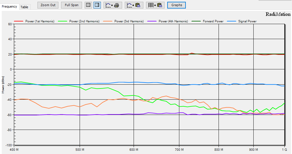
Test results
In the test results it is possible to show the forward power measured.
When only a spectrum analyser is used, the forward power will be the same as the first harmonic. When also a broadband power meter is used, the forward power measurement will be the measured broadband power, and it thus will be higher than the power of the first harmonic alone.
For more information on how to perform the measurement of amplifier harmonics, please see the EUT Harmonics section in Chapter 12 of the RadiMation® manual.

