File list
This special page shows all uploaded files.
| Date | Name | Thumbnail | Size | Description | Versions |
|---|---|---|---|---|---|
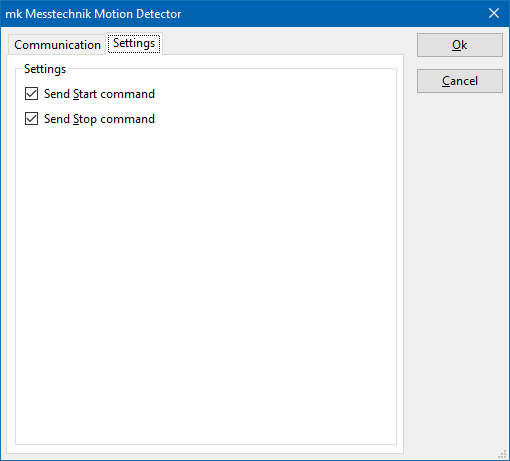
| 13:17, 14 May 2020 | MkMesstechnikMotionSettings.png (file) |  |
6 KB | A screenshot of the mk Messtechnik motion detection device driver, where the settings of the device driver can be configured. Also see: mk Messtechnik Motion Detector Category:Screenshot | 1 |
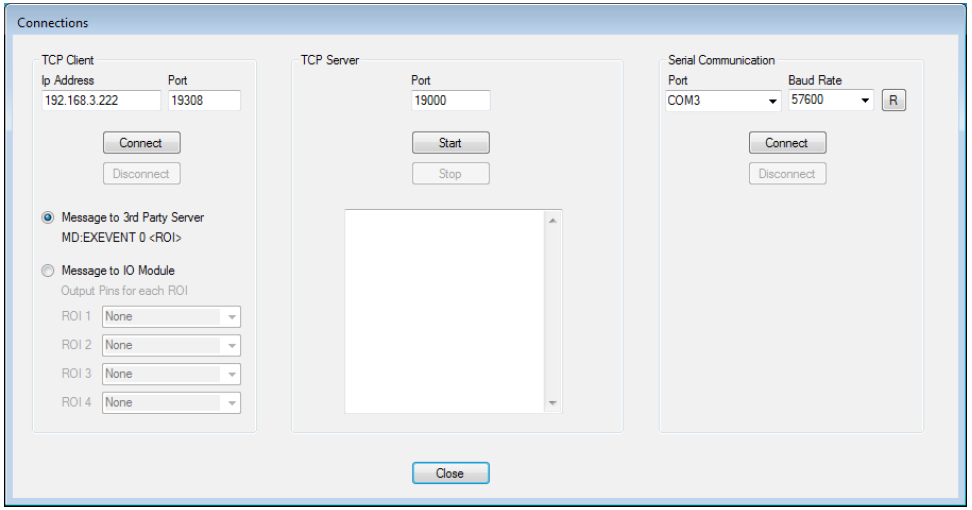
| 13:15, 14 May 2020 | MkMesstechnikMotionServerSettings.png (file) |  |
49 KB | The configuration settings on the server software of the mk Messtechnik motion detection software. This is thus a dialog of the software of mk Messtechnik. This is not a dialog that is part of our {{RadiMation}} software. | 1 |
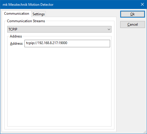
| 13:14, 14 May 2020 | MkMesstechnikMotionCommunication.png (file) |  |
6 KB | The communication settings dialog, to configure the communication with the mk Messtechnik Motion detection server. | 1 |
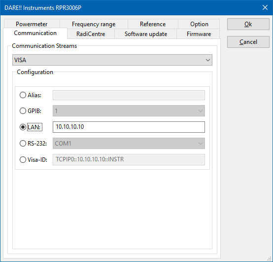
| 13:52, 3 January 2020 | VISA DeviceStream Configuration.png (file) |  |
14 KB | Screenshot of the VISA DeviceStream configuration dialog Category:Screenshot | 1 |
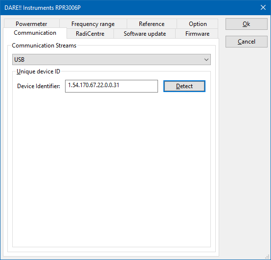
| 13:52, 3 January 2020 | USB DeviceStream Configuration.png (file) |  |
10 KB | Screenshot of the USB DeviceStream configuration dialog Category:Screenshot | 1 |
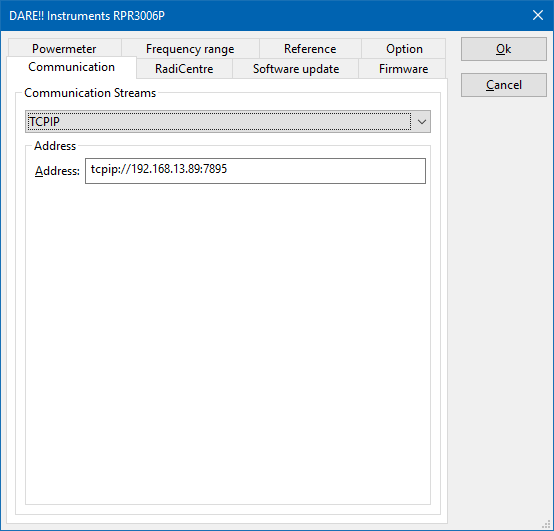
| 13:51, 3 January 2020 | TCPIP DeviceStream Configuration.png (file) |  |
10 KB | Screenshot of the TCPIP DeviceStream configuration dialog Category:Screenshot | 1 |
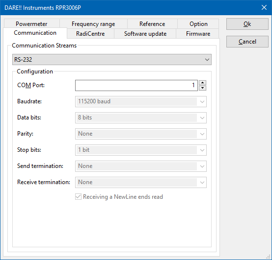
| 13:51, 3 January 2020 | RS-232 DeviceStream Configuration.png (file) |  |
13 KB | Screenshot of the RS-232 DeviceStream configuration dialog Category:Screenshot | 1 |
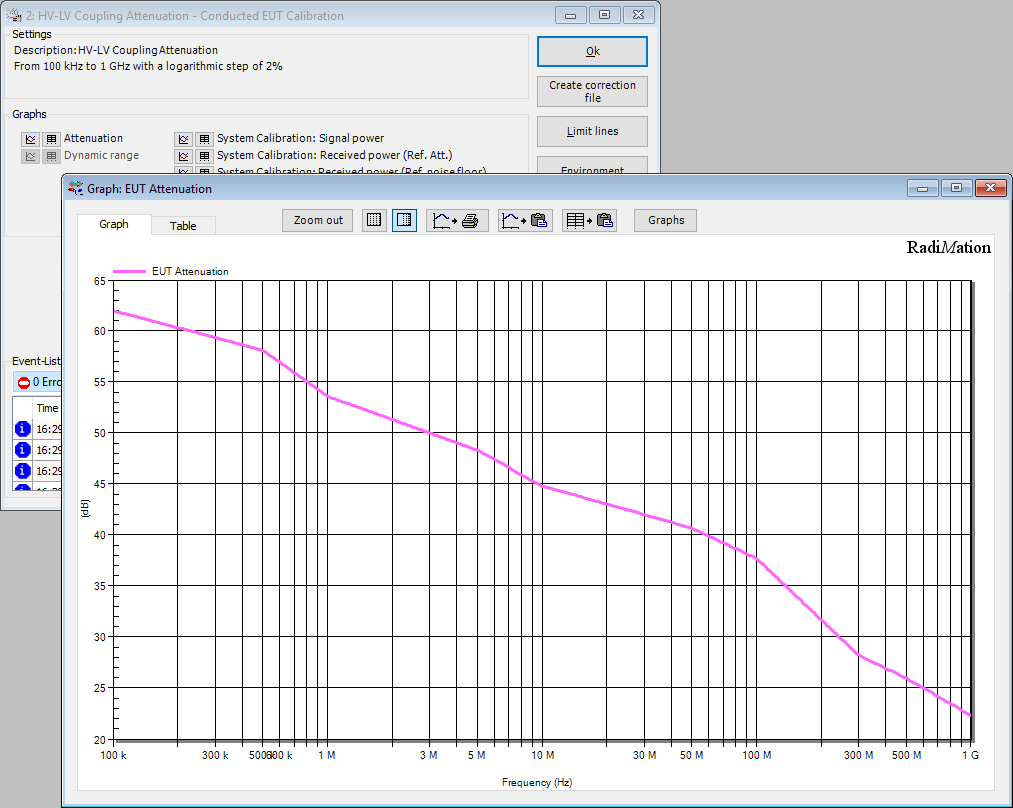
| 14:49, 10 April 2019 | HV-LVAttenuationGainEUTCalibrationResultGraph.png (file) |  |
67 KB | The window that is shown to present the result of the Attenuation/Gain EUT calibration, also showing the EUT Attenuation graph. In this example specifically for the HV-LV Attenuation measurement. | 1 |
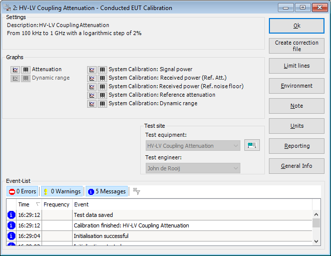
| 14:46, 10 April 2019 | HV-LVAttenuationGainEUTCalibrationResult.png (file) |  |
25 KB | The window that is shown to present the result of the Attenuation/Gain EUT calibration. In this example specifically for the HV-LV Attenuation measurement. | 1 |
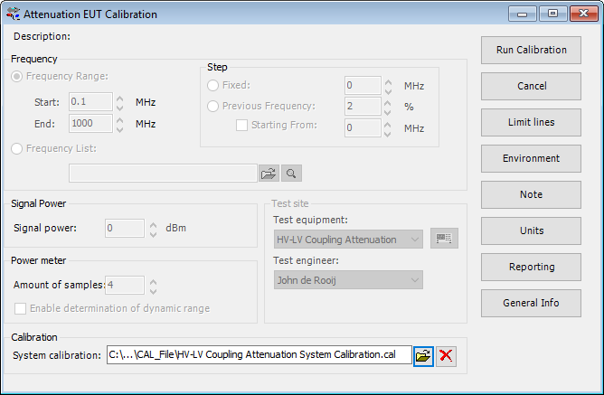
| 14:04, 10 April 2019 | HV-LVCouplingAttenuationEUTCalibrationTSF.png (file) |  |
23 KB | Screenshot of the TSF configuration dialog of the Attenuation/Gain EUT calibration, where it is configured to perform a measurement of the HV-LV Coupling attenuation. | 1 |
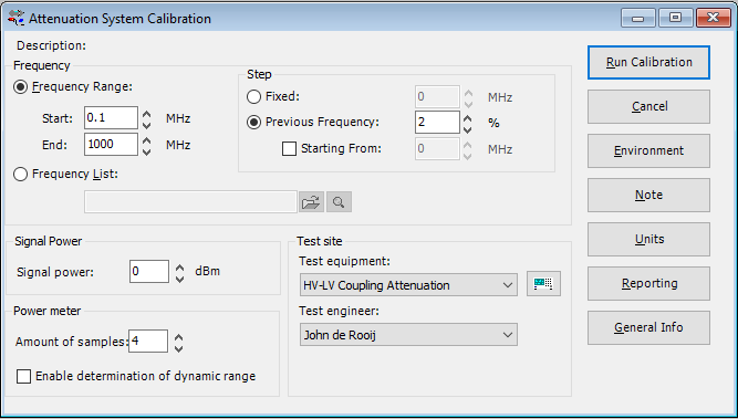
| 13:06, 10 April 2019 | HV-LVCouplingAttenuationSystemCalibrationTSF.png (file) |  |
18 KB | Screenshot of the TSF configuration dialog of the Attenuation/Gain System calibration, where it is configured to perform a measurement of the HV-LV Coupling attenuation. | 1 |
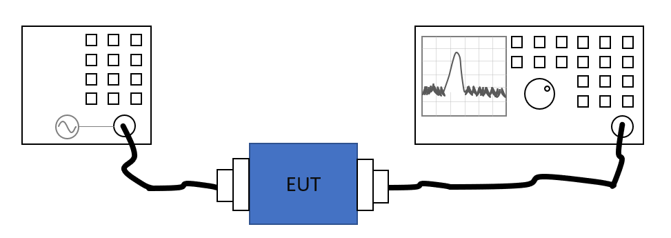
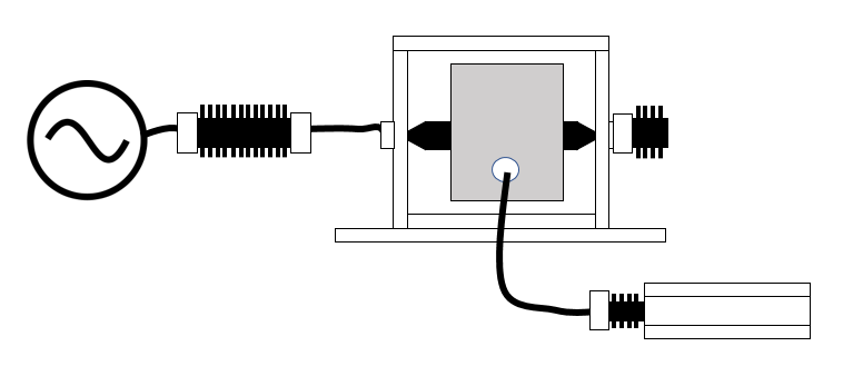
| 12:52, 10 April 2019 | HV-LVAttenuationGainEUTCalibration.png (file) |  |
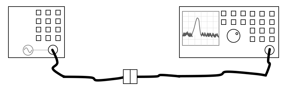
19 KB | HV-LV Coupling Attenuation measurement, using the Attenuation/Gain EUT calibration, using a setup with a signal generator and a spectrum analyzer. | 1 |
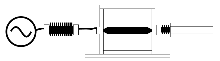
| 12:51, 10 April 2019 | AttenuationGainSystemCalibration.png (file) |  |
19 KB | Setup of the Attenuation/Gain System calibration, using a signal generator and a spectrum analyzer | 1 |
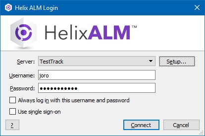
| 06:54, 25 February 2019 | TestTrackStudioLogIn.jpg (file) |  |
31 KB | 2 | |
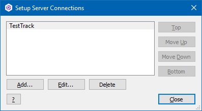
| 06:53, 25 February 2019 | TestTrackSetupServerConnection.jpg (file) |  |
20 KB | 2 | |
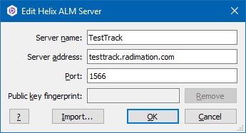
| 06:52, 25 February 2019 | TestTrackServerSettings.jpg (file) |  |
24 KB | 4 | |
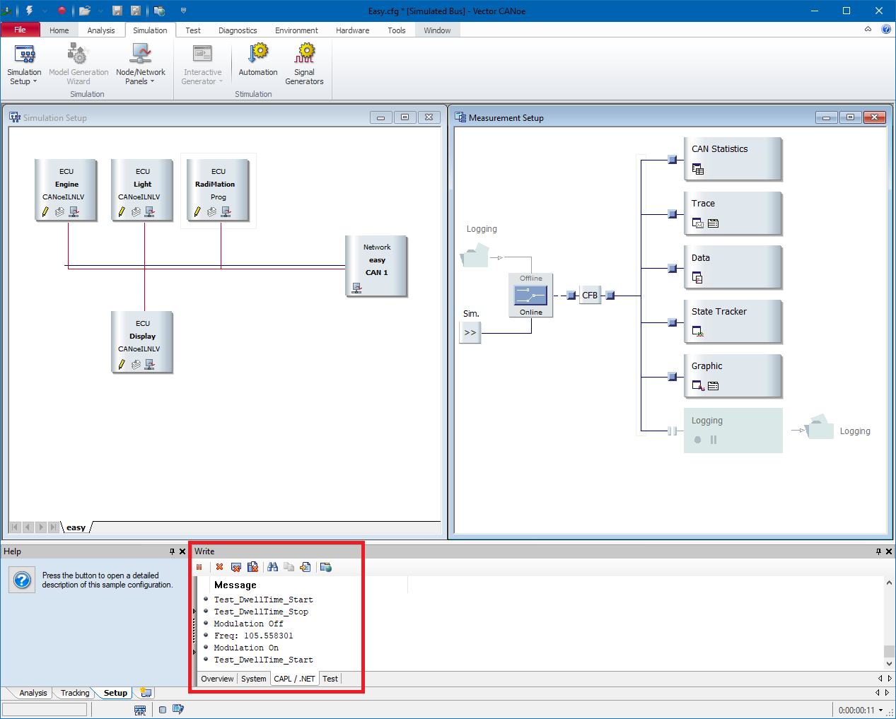
| 12:57, 15 February 2019 | CANoe CAPL messages.png (file) |  |
72 KB | Shows the Simulation Setup view of the CANoe software, which shows the RadiMationInterface.can node, which is controlled by the CANoe Switch Matrix device driver to show messages. The area that shows the messages is highlighted. | 1 |
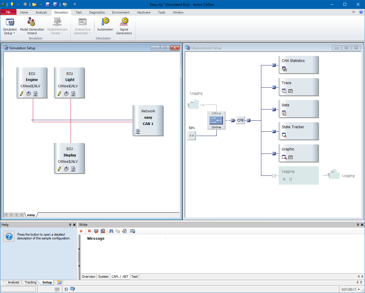
| 12:42, 15 February 2019 | CANoe Simulation setup.png (file) |  |
66 KB | A screenshot of the CANoe software that shows the Simulation setup of the EASY.CFG example. | 1 |
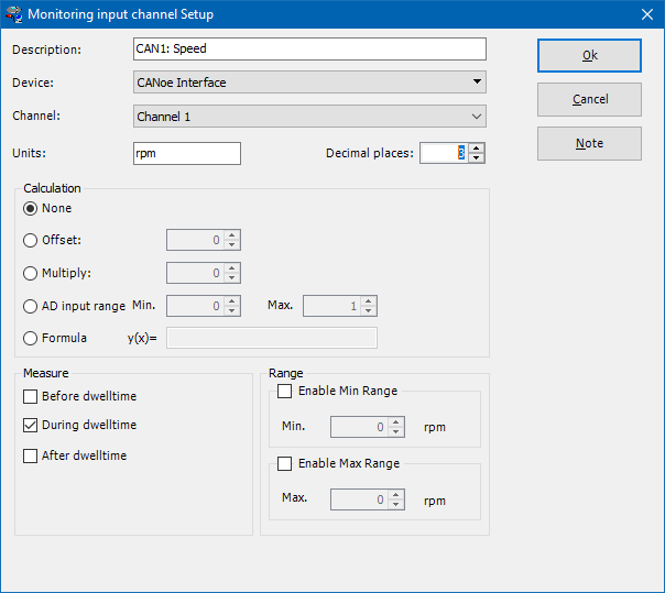
| 10:23, 15 February 2019 | CANoe EUT Monitoring Input Setup.png (file) |  |
22 KB | Shows the EUT Monitoring Input setup dialog, with the configuration for a CANoe Interface device driver. | 1 |
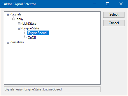
| 10:15, 15 February 2019 | CANoe AD Convertor signal selector.png (file) |  |
9 KB | Shows the dialog that allows to select a signal from the CANoe software. | 1 |
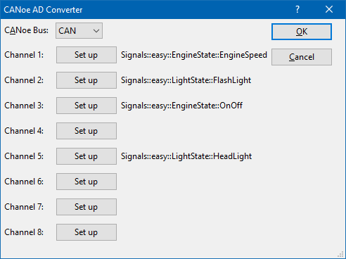
| 10:11, 15 February 2019 | CANoe AD Convertor.png (file) |  |
12 KB | Show an example of the CANoe Interface advanced configuration dialog, with some selected CANoe signals. | 2 |
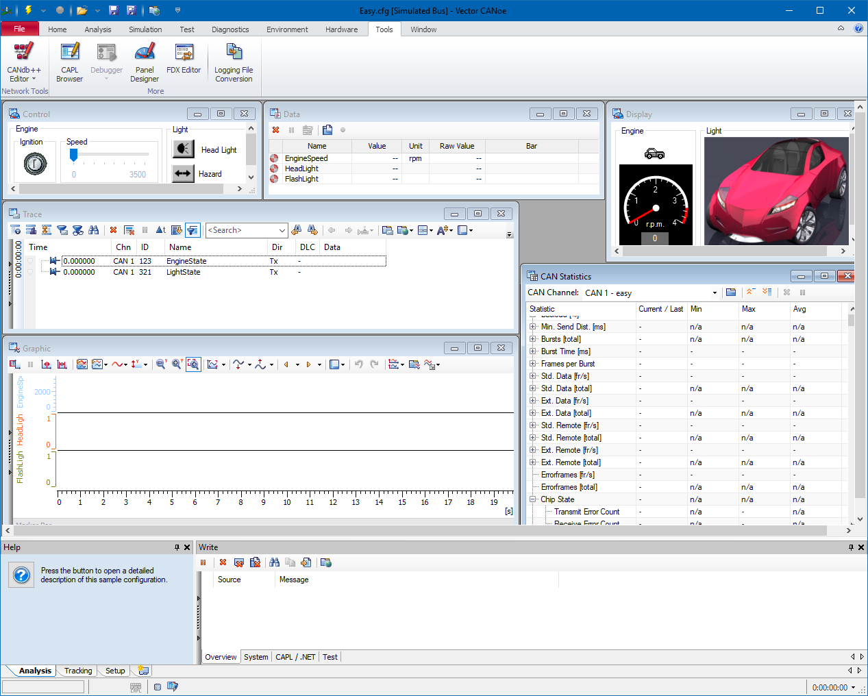
| 10:03, 15 February 2019 | CANoeExample.png (file) |  |
211 KB | Shows a screenshot of the CANoe software, which has the 'EASY.CFG' example loaded. | 1 |
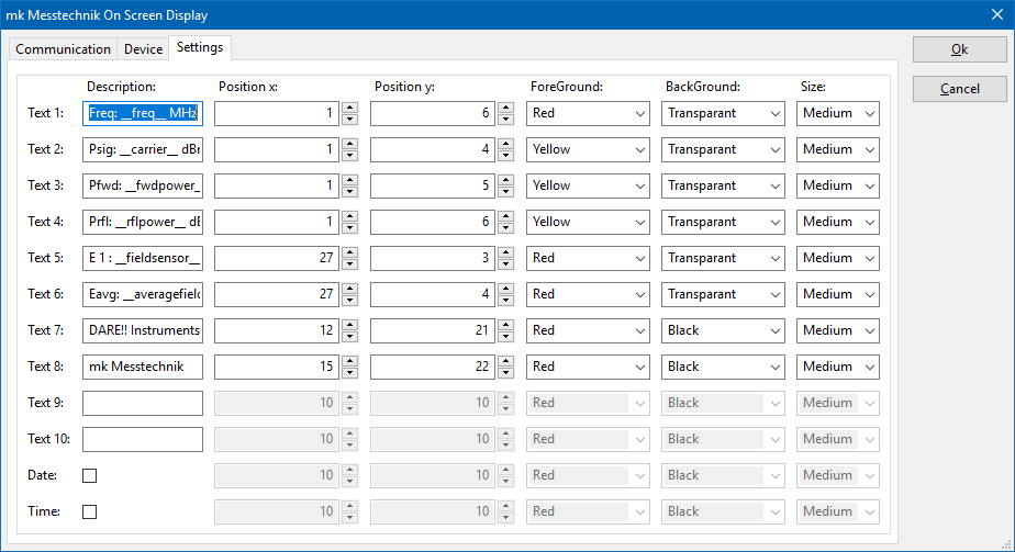
| 11:14, 30 January 2019 | MkMesstechnikOnScreenDisplaySettings.png (file) |  |
30 KB | Screenshot of the Display tab of the Mk Messtechnik On Screen Display driver. | 1 |
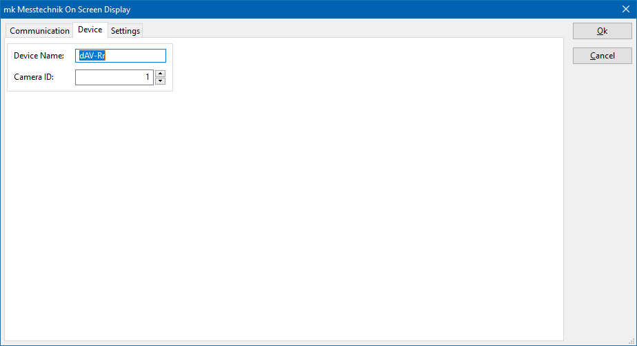
| 11:14, 30 January 2019 | MkMesstechnikOnScreenDisplayDevice.png (file) |  |
8 KB | Screenshot of the Device tab of the Mk Messtechnik On Screen Display driver. | 1 |
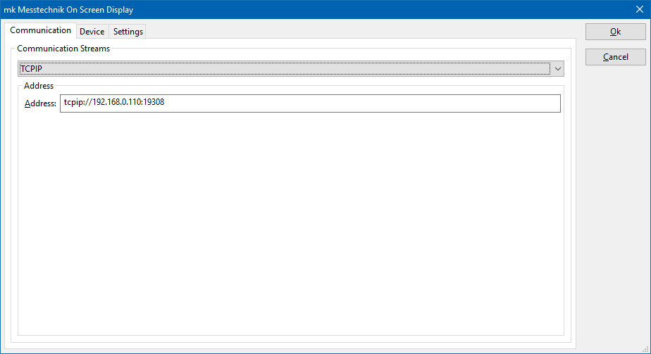
| 11:13, 30 January 2019 | MkMesstechnikOnScreenDisplayCommunication.png (file) |  |
8 KB | Screenshot of the Communication tab of the Mk Messtechnik On Screen Display driver. | 1 |
| 14:13, 29 January 2019 | CurrentSensorCalibrationSystemCalibration.png (file) |  |
11 KB | System calibration setup of the Current sensor calibration, as it is described in RadiMation Application Note 104 | 1 |
| 14:12, 29 January 2019 | CurrentSensorCalibrationEUTCalibration.png (file) |  |
13 KB | Measurement setup of the Current sensor calibration, as it is described in RadiMation Application Note 104 | 1 |
| 19:33, 8 October 2018 | Schwarzbeck BBV 9745 front.jpg (file) |  |
1.14 MB | 1 | |
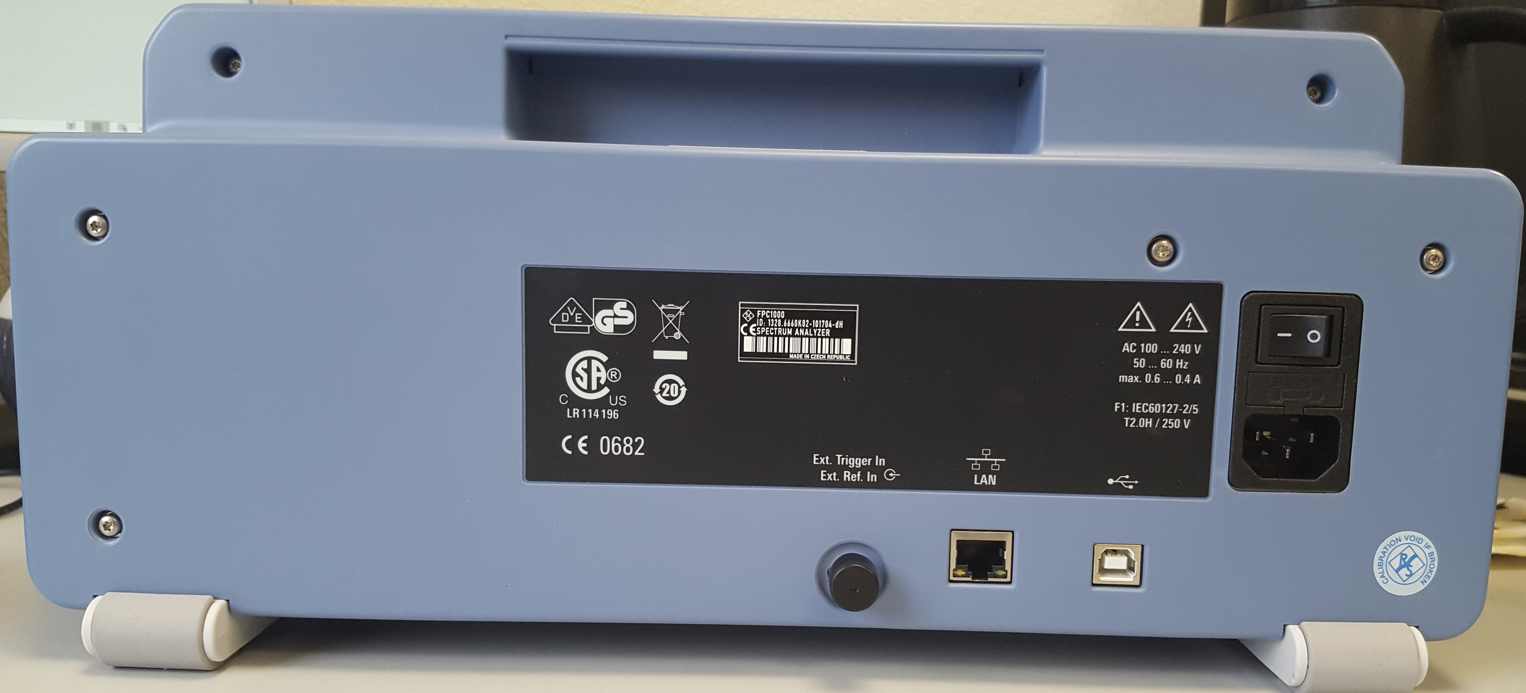
| 14:35, 8 October 2018 | Rohde & Schwarz FPC1000 back.jpg (file) |  |
1.97 MB | 1 | |
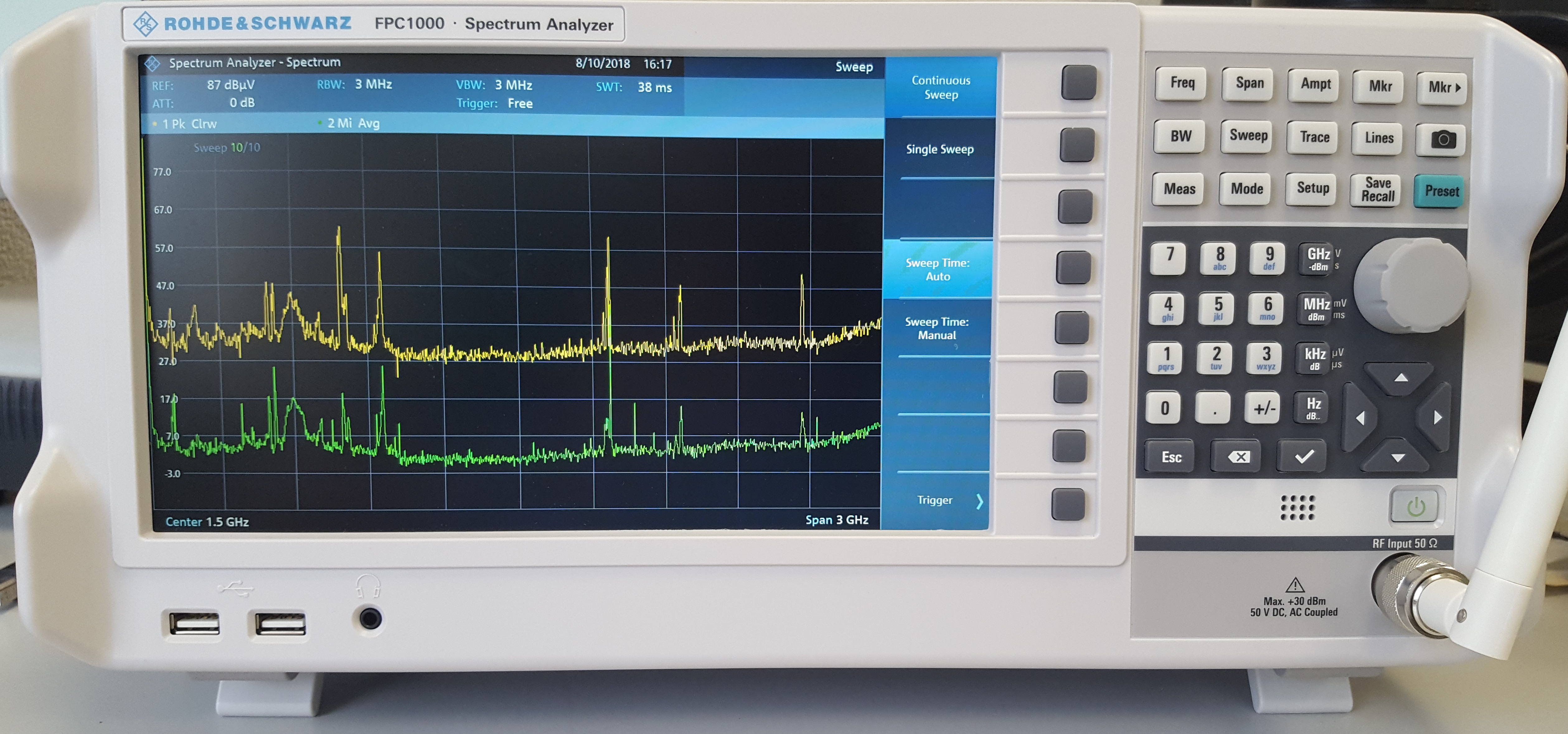
| 14:34, 8 October 2018 | Rohde & Schwarz FPC1000 front.jpg (file) |  |
2.59 MB | 1 | |
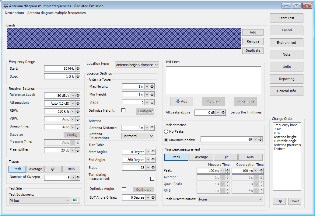
| 11:54, 23 April 2018 | AN103 AntennaDiagramTSFMultipleFrequencies.png (file) |  |
66 KB | Configuration of the TSF for the antenna diagram measurement, as it is explained in the RadiMation Application Note 103. In this configuration however multiple peaks on multiple frequencies will be measured, and the turntable is already rotated by 10 | 1 |
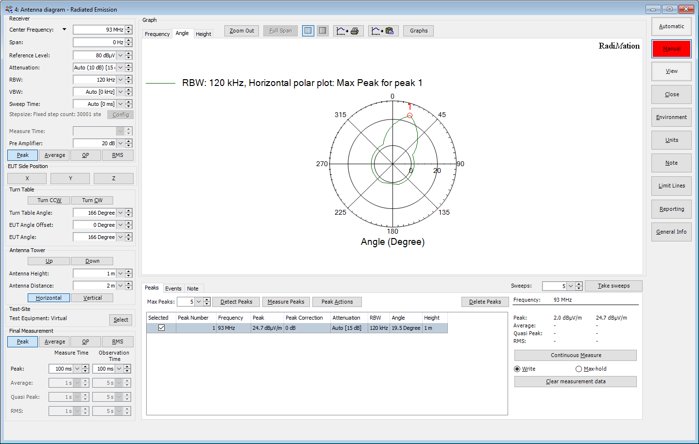
| 11:33, 23 April 2018 | AN103 AntennaDiagramFinalPolarPlotGraph.png (file) |  |
93 KB | Final polar plot graph of the antenna diagram measurement, as it is explained in the RadiMation Application Note 103 | 1 |
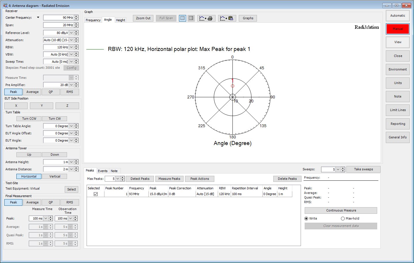
| 11:19, 23 April 2018 | AN103 AntennaDiagramPolarPlotGraph.png (file) |  |
88 KB | Initial (empty) polar plot graph of the antenna diagram measurement, as it is explained in the RadiMation Application Note 103 | 1 |
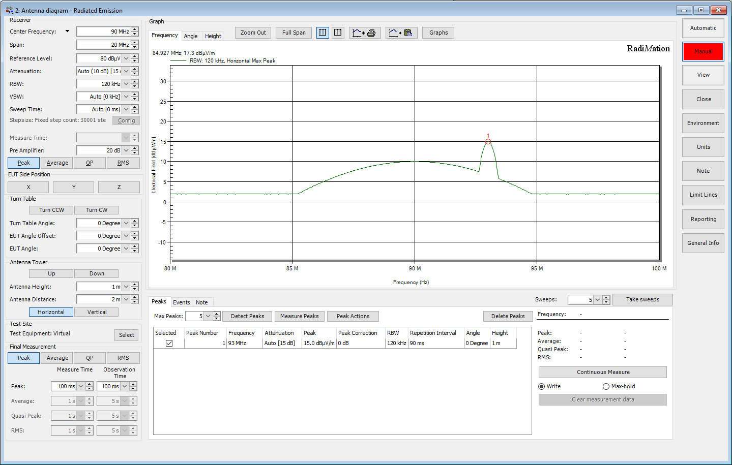
| 11:16, 23 April 2018 | AN103 AntennaDiagramFrequencyGraph.png (file) |  |
80 KB | 2 | |
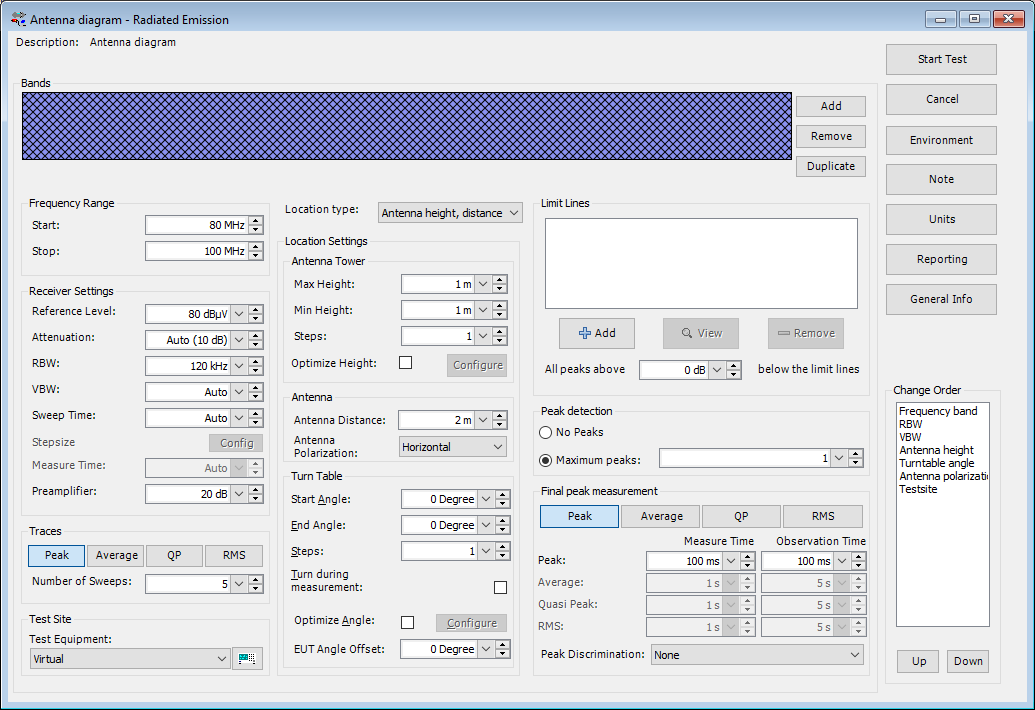
| 11:06, 23 April 2018 | AN103 AntennaDiagramTSF.png (file) |  |
55 KB | Configuration of the TSF for the antenna diagram measurement, as it is explained in the RadiMation Application Note 103 | 1 |
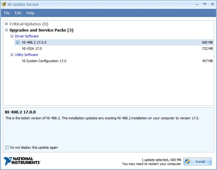
| 10:54, 29 August 2017 | NIUpdateServiceSelected.png (file) |  |
28 KB | Screenshot of the 'NI Update Service' program that shows that the NI488.2M software update is selected. | 1 |
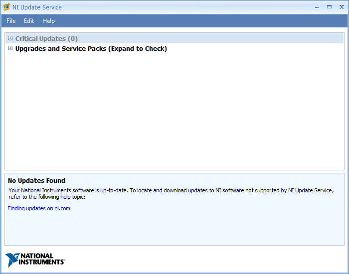
| 10:53, 29 August 2017 | NIUpdateServiceCollapsed.png (file) |  |
17 KB | Screenshot showing the 'NI Update Service', which still has the 'Service Packs' section collapsed. | 1 |
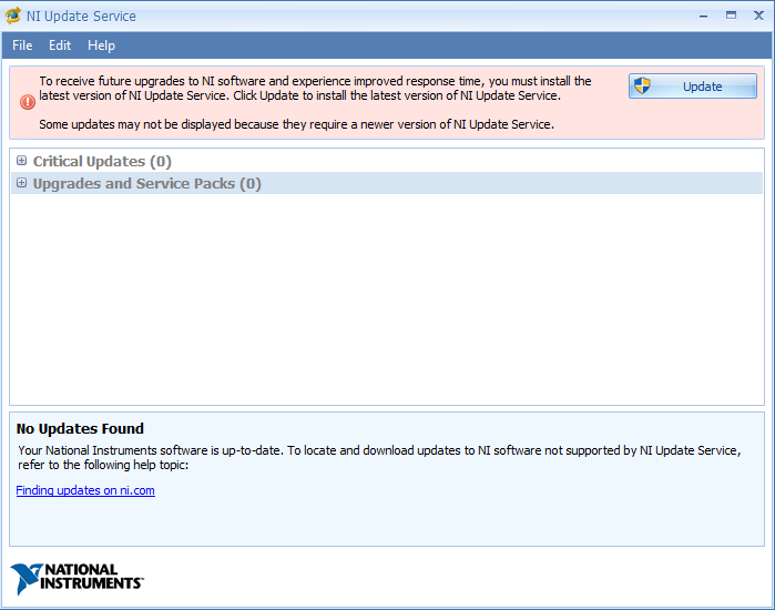
| 10:46, 29 August 2017 | NIUpdateServiceUpdate.png (file) |  |
25 KB | A Screenshot of the 'NI Update Service' program, that needs an update itself. | 1 |
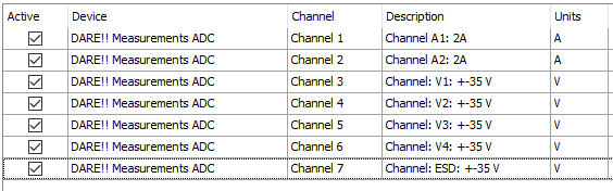
| 11:14, 1 December 2016 | DARE!! Measurements ADC Configuration.png (file) |  |
9 KB | Screenshot of the EUT Monitoring channels configuration of the DARE!! Measurements ADC. | 1 |
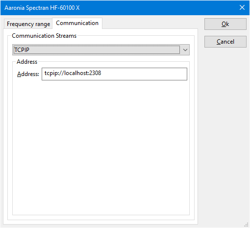
| 09:20, 8 September 2016 | AaroniaSpectran Driver communication.png (file) |  |
8 KB | A screenshot of the 'Communication' tab of the [[Aaronia Spectran] device driver. | 1 |
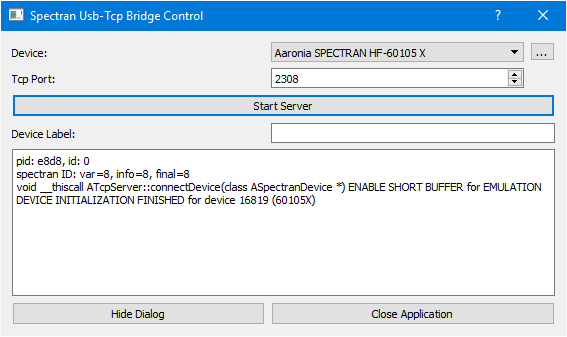
| 08:59, 8 September 2016 | SpectranUSBTCPBridge started.png (file) |  |
10 KB | A screenshot of the started Aaronia Spectran USB-TCP Bridge software. | 1 |
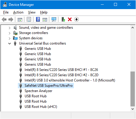
| 11:52, 31 August 2016 | Windows Device Manager Safenet USB.png (file) |  |
18 KB | A screenshot of the windows device manager that shows that the Safenet USB Dongle is available in the list of connected USB devices | 1 |
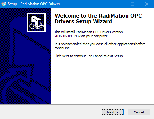
| 12:56, 9 June 2016 | OPCDriversExeStartPage.png (file) |  |
14 KB | An example of the start screen of the OPC_DRIVERS.EXE setup wizard. | 1 |
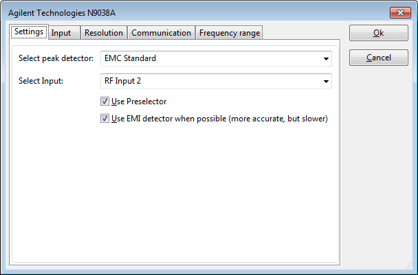
| 16:17, 18 February 2016 | Agilent N9038A Settings Tab.png (file) |  |
12 KB | The {{ScreenElement|Settings}} tab of the Agilent Technologies N9038A device | 1 |
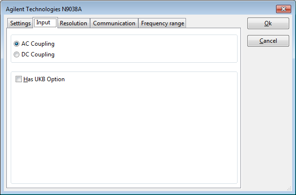
| 16:17, 18 February 2016 | Agilent N9038A Input Tab.png (file) |  |
12 KB | The {{ScreenElement|Input}} tab of the Agilent Technologies N9038A device. | 1 |
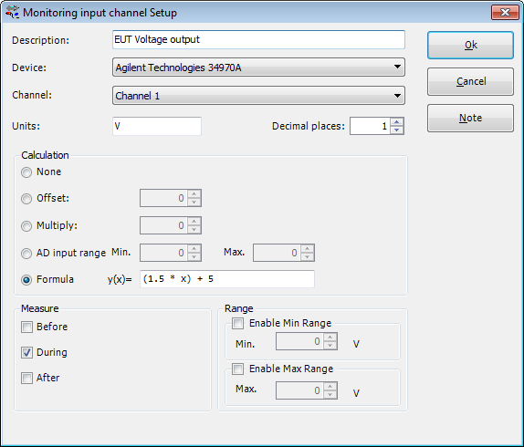
| 07:28, 28 April 2015 | ADChannelInputConfiguration.png (file) |  |
19 KB | 1 | |
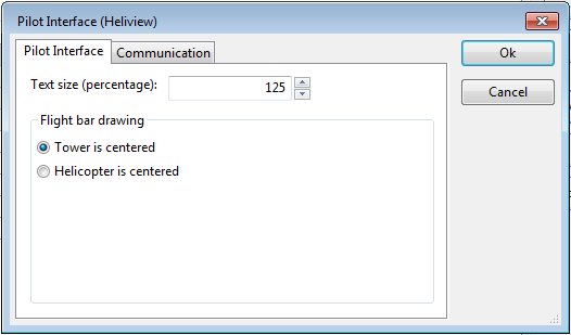
| 12:08, 11 December 2014 | Pilot interface device driver configuration.png (file) |  |
10 KB | A screenshot of the pilot interface device driver configuration | 1 |
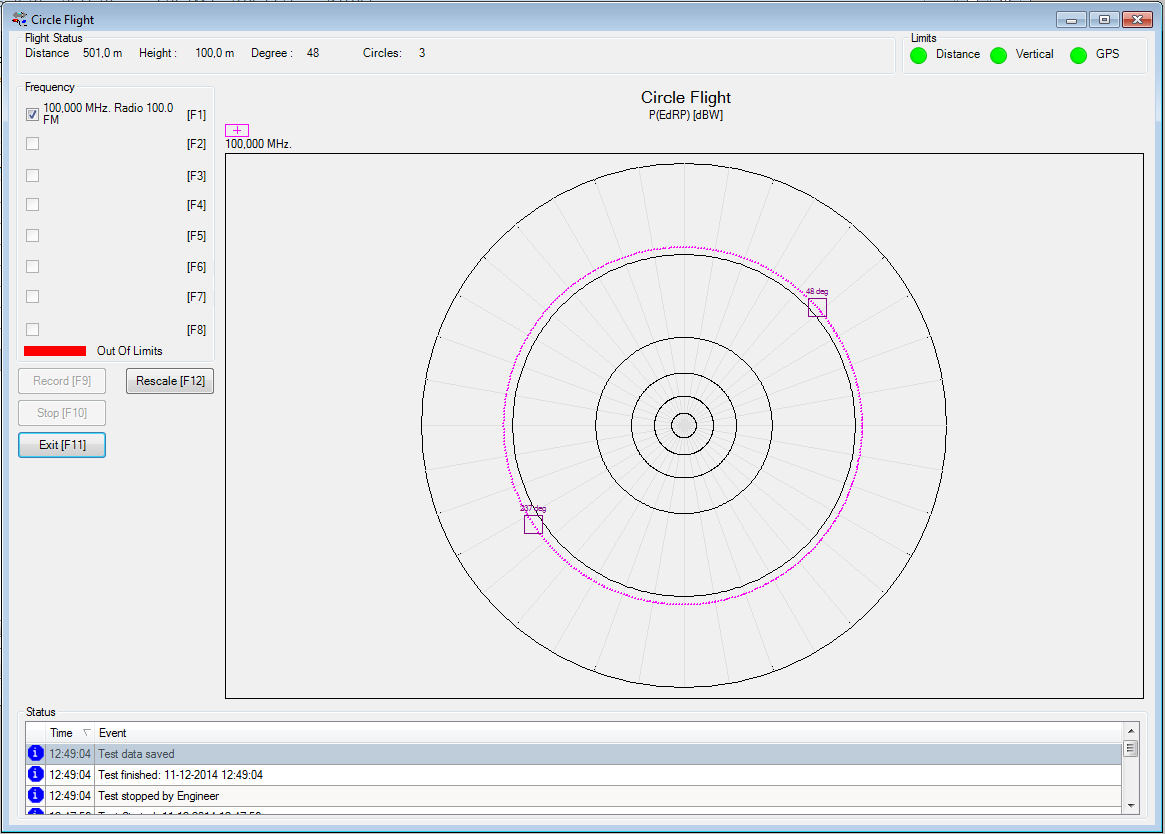
| 11:49, 11 December 2014 | Antenna Diagram Circle Flight Test Result Window.png (file) |  |
53 KB | 2 | |
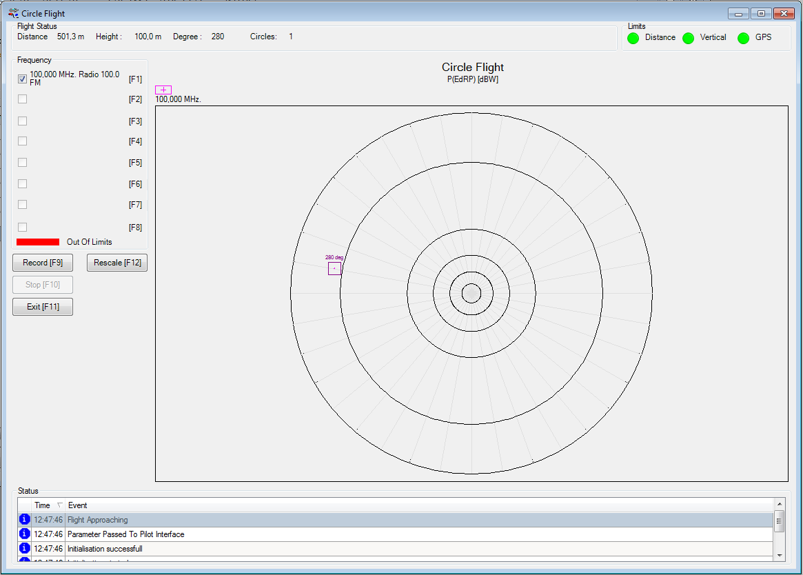
| 11:48, 11 December 2014 | Antenna Diagram Circle Flight Test Window.png (file) |  |
51 KB | 2 | |
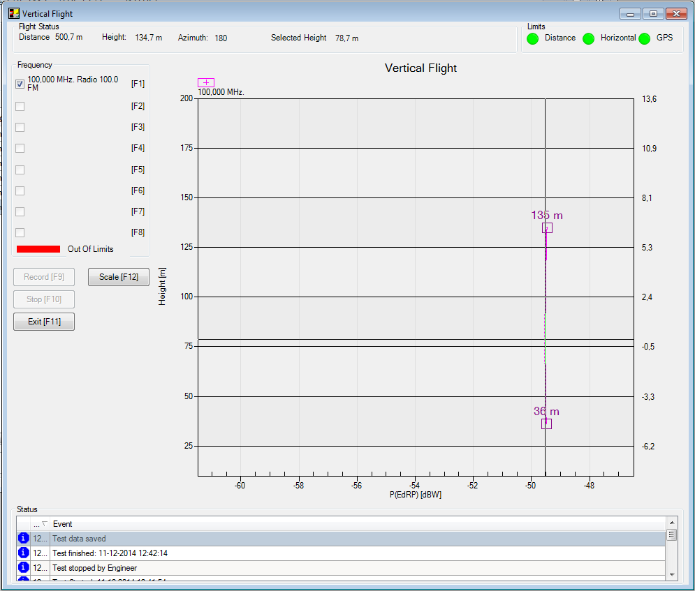
| 11:44, 11 December 2014 | Antenna Diagram Vertical Flight Test Result Window.png (file) |  |
37 KB | 2 |