Chapter 14: Difference between revisions
| (212 intermediate revisions by 8 users not shown) | |||
| Line 1: | Line 1: | ||
__NOTOC__ | __NOTOC__ | ||
=Configuration= | = Configuration = | ||
The global configuration of {{RadiMation}} is available in the menu | |||
{{Menu|Configuration}} | |||
[[Image:Configuration pull down menu.png]] | |||
The | The configured global {{RadiMation}} configuration will be used as the configuration for future use. This configuration is independent of the actual Windows User Account that is logged on to the Microsoft Windows PC. The configured global {{RadiMation}} configuration is shared and accessible for all Windows User Accounts that have access to the PC. | ||
The following paragraphs will explain all the possible configurations. | |||
To prevent unauthorised | {{Warning|To prevent unauthorised individuals from changing the global {{RadiMation}} configurations, a password protection can be used for specific engineers. The password is activated by default for the "'''Administrator'''" engineer with the password "'''Radimation'''". This password protection can be switched off, changed and configured in the menu | ||
{{Menu|Configuration| | {{Menu|Configuration|Engineers|Edit}} | ||
}} | |||
=== | == Engineers == | ||
On a new installation, only a single 'Administrator' engineer is created by default. An unlimited number of engineers can be added, each with an unique name. For each engineer a login password and different permissions can be assigned which give them the right to modify specific parts of the {{RadiMation}} configuration. There is no relation between the engineer in {{RadiMation}} and the Windows Logon account. Also the password that can be configured for the engineer in {{RadiMation}} is not linked and also not synchronized with the Windows User account password. | |||
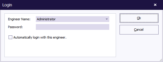
During the startup of {{RadiMation}} the actual engineer that is going to start tests can be selected in the {{WindowTitle|Login}} dialog. If a password is configured for that engineer, it should also be specified at that moment. | |||
[[Image:Login.png]] | |||
Automatic login of the engineer can be disabled or enabled. If it is enabled, it can only be selected for one engineer, and that engineer will be automatically logged in the next time that {{RadiMation}} starts. If the {{ScreenElement|Automatically login with this engineer}} checkbox is selected for an engineer, the automatic login of all the other engineers will not be performed anymore. For changing setting of the the automatically logged in engineer, it is still necessary to close the login dialog by specifying the corresponding {{ScreenElement|Password}} and using the {{ScreenElement|Ok}} button. | |||
Switching between the active engineers while {{RadiMation}} is running can be done through the menu: | |||
{{Menu|File|Change Engineer}} | |||
[[Image:File Change Engineer.png]] | |||
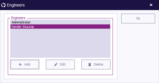
To add, delete or edit the names and permissions of the engineers, go to the {{ScreenElement|Engineers}} window, which can be accessed in the menu: | |||
{{Menu|Configuration|Engineers}} | |||
[[Image:Config engineers.png]] | |||
=== | The Engineers window will open and show the current configured list of engineers. | ||
=== Test engineer settings === | |||
To leave the 'Engineers' window, click {{ScreenElement|OK}}. | |||
==== Adding an engineer ==== | |||
To add a new test engineer to the configuration, click {{ScreenElement|Add}}. | |||
[[Image:Engineer add engineer.png]] | |||
Enter the name and set the rights of the new engineer, then click {{ScreenElement|OK}}. You will be returned to the 'Engineers' window. | |||
The new engineer will not have a protection password (yet), this can be enabled by clicking {{ScreenElement|[[Change Password]]}}. Please read the paragraph 'Password protection' (located further down) for more information. | |||
* | |||
[[Image:Test engineer add engineer.png]] | |||
==== Deleting an engineer ==== | |||
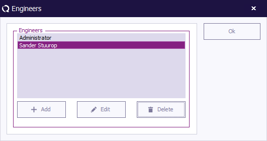
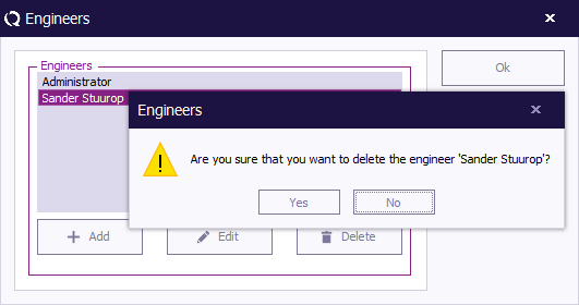
To delete a test engineer from the configuration, select the engineer and click {{ScreenElement|Delete}}. | |||
[[Image:Engineer delete engineer.png]] | |||
To confirm that you want to delete the engineer from the configuration list, click {{ScreenElement|Yes}}. | |||
If you do not want to delete this engineer from the list, click {{ScreenElement|No}} or {{ScreenElement|Cancel}}. You will be returned to the 'Engineers' window. | |||
[[Image:Engineer delete engineer confirm.png]] | |||
==== Editing engineer settings ==== | |||
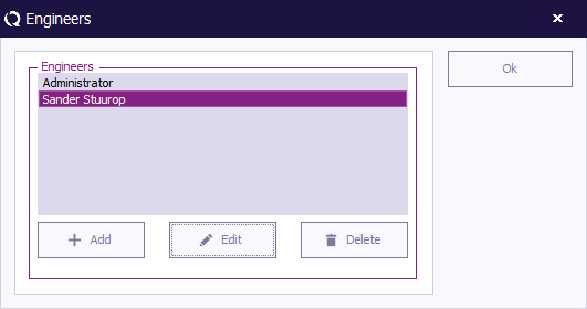
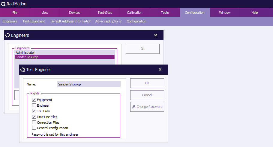
To edit the name, rights and/or password of an engineer in the configuration, select the engineer and click {{ScreenElement|Edit}}. | |||
[[Image:Engineer edit engineer.png]] | |||
Make the desired changes in the 'Test Engineer' window and click {{ScreenElement|OK}}. | |||
If you want to undo or cancel your changes, click {{ScreenElement|Cancel}}. You will be returned to the 'Engineers' window. | |||
[[Image:Test engineer edit engineer.png]] | |||
=== Password protection === | |||
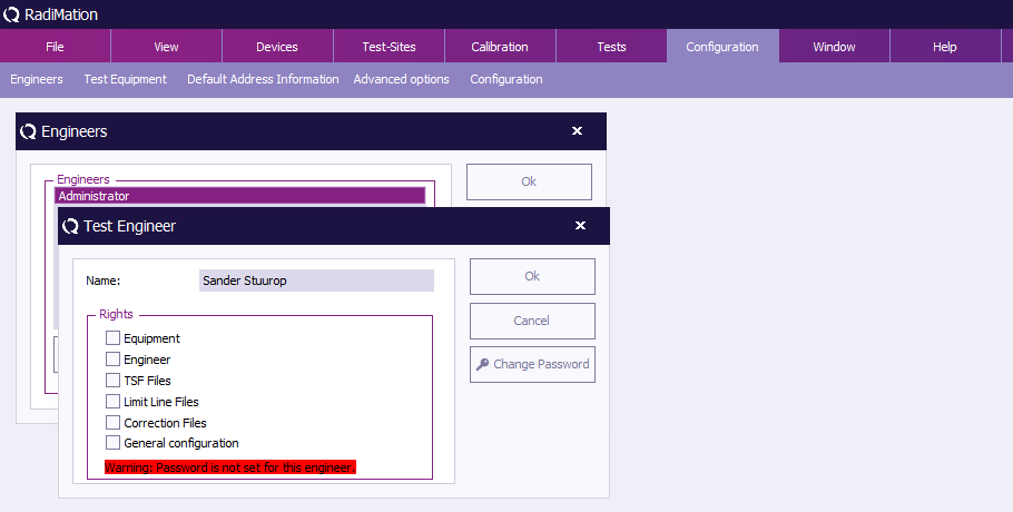
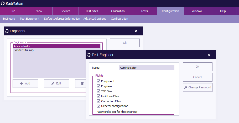
{{RadiMation}} allows you to protect a number of configurations with a password. This password can be enabled, disabled or changed in the {{ScreenElement|'Test Engineer' window}}. | |||
* The password is standard turned on for the default used test engineer 'Administrator'. | |||
* The default password is '''Radimation'''. | |||
The current password setting for the selected engineer is displayed at the bottom of this window. This will indicate whether a password has been 'set' or 'not set'. | |||
[[Image:Test engineer.png]] | |||
==== Rights ==== | |||
The password protection can be enabled or disabled for the following items. | |||
{{ScreenElementDescriptionStart}} | |||
{{ScreenElementDescription|Equipment|Prevents unauthorized changes to test equipment configuration.}} | |||
{{ScreenElementDescription|Engineer|Prevents unauthorized changes to test engineers configuration.}} | |||
{{ScreenElementDescription|TSF Files|Prevents unauthorized changes to [[Test Setup File]]s (TSF) files.}} | |||
{{ScreenElementDescription|Limit Line|Prevents unauthorized changes to [[Chapter 18|Limit Line File]]s (LLF) files.}} | |||
{{ScreenElementDescription|Correction File|Prevents unauthorized changes to correction files.}} | |||
{{ScreenElementDescription|General Configuration|Prevents unauthorized changes to the general configuration.}} | |||
{{ScreenElementDescriptionEnd}} | |||
==== Change password ==== | |||
To enable, disable or change the password, click {{ScreenElement|[[Change Password]]}}. | |||
[[Image:Test engineer.png]] | |||
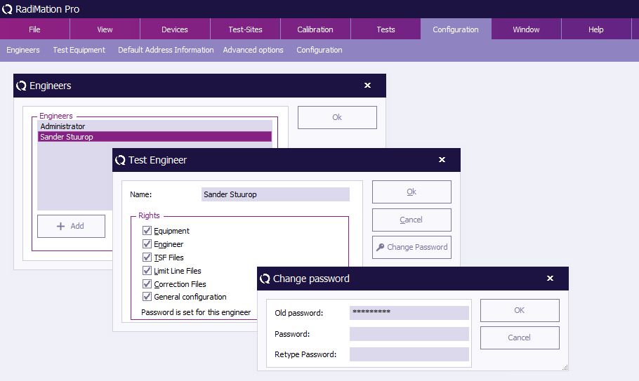
To change the password, enter the old password and the new password (twice), then click {{ScreenElement|OK}}. You will be returned to the 'Test Engineer' window. | |||
[[Image:Change password.png]] | |||
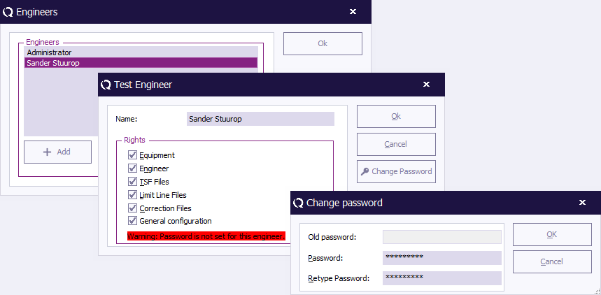
To disable the password, enter the old password and leave the two new password fields empty, then click {{ScreenElement|OK}}. You will be returned to the 'Test Engineer' window, and the password indication will change to: “Warning: Password is not set for this engineer.” | |||
[[Image:Disable password.png]] | |||
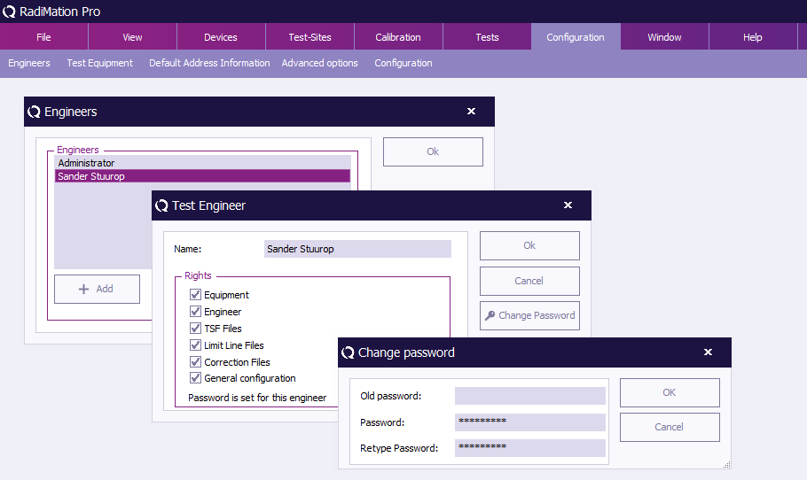
To enable the password, enter the new password (twice), then click {{ScreenElement|OK}}. You will be returned to the 'Test Engineer' window, and the password indication will change to: “Password is set for this engineer.” | |||
[[Image:Enable password.png]] | |||
To leave the 'Engineers' window, click {{ScreenElement|OK}}. | |||
== Test Equipment == | |||
The test equipment configuration contains a list of all the test equipment used during a test. The software uses this list to determine which device drivers should be used to control the test equipment. {{RadiMation}} allows you to configure specific test equipment lists for each type of test as well as different test equipment lists for the same type of tests. (This can be useful if you have, for example, more than one signal generator to perform conducted immunity tests with). | |||
{{ | In the ''' 'Test Equipment' window''' a set of test equipment will be selected. When a calibration file is generated, {{RadiMation}} will record this test equipment configuration together with the calibration data. When a substitution test is started, the test equipment selected for the substitution test will be compared with the test equipment used (as recorded) during the calibration test. If the equipment does not match, an error message will be displayed. | ||
The error message window will ask you to abort the test or to ignore the error message and continue the test with different test equipment. To achieve maximum accuracy, the same test equipment should be used (whenever possible) during both the calibration and the substitution tests. | |||
To add, modify or delete test equipment lists, go to the ''' 'Test Equipment' window''' in the ''' 'Configuration' tab'''. | |||
[[Image:Config test equipment.png]] | |||
The 'Test Equipment' window will open and show the current configured list of test equipment. To leave the 'Test Equipment' window, click ''' 'Close' '''. | |||
=== Adding test equipment === | |||
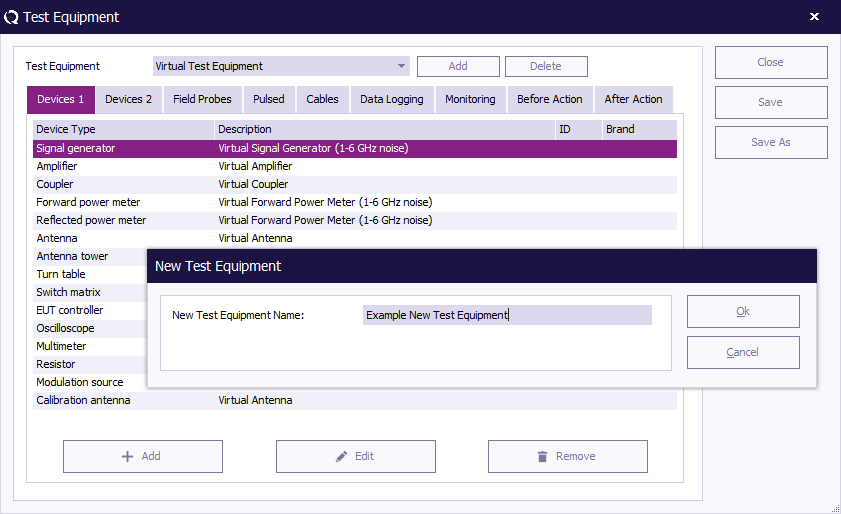
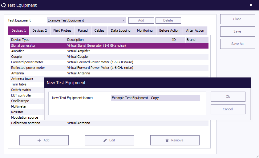
To add a (set of) test equipment to the configuration, click the ''' 'Add' ''' button in the top of the window. The 'New Test Equipment' window will appear. | |||
Enter a name for the new test equipment in the ''' 'New Test Equipment' ''' window (e.g. Example Test Equipment). | |||
Click ''' 'OK' ''' to confirm the name of the new test equipment, or click ''' 'Cancel' ''' to cancel the new name. You will be returned to the 'Test Equipment' window. | |||
[[Image:New test equipment.png]] | |||
=== Deleting test equipment === | |||
=== | |||
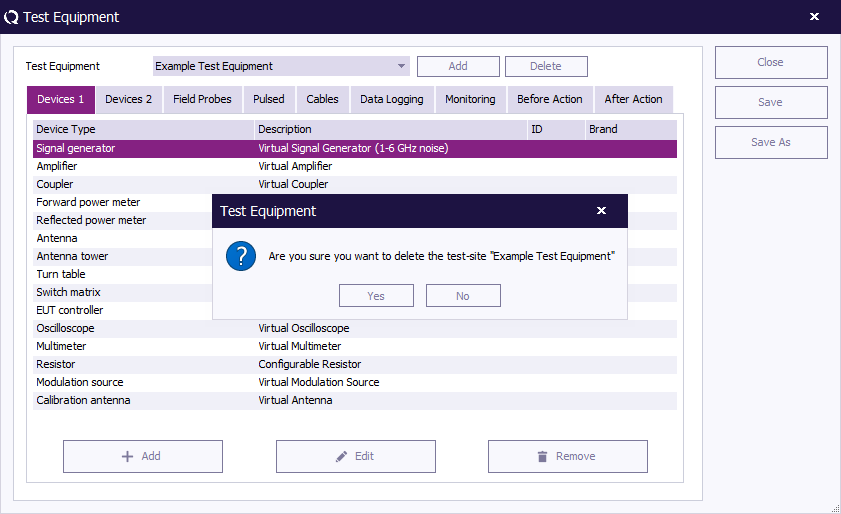
To delete a (set of) test equipment from the configuration, select the '''Test Equipment''' from the pull down menu and click the ''' 'Delete' button''' in the top of the window. A confirmation window will appear. | |||
Click ''' 'Yes' ''' to remove the device from the list, click ''' 'Cancel' ''' to cancel. You will be returned to the 'Test Equipment' window. | |||
[[Image:Delete test equipment.png]] | |||
=== Editing test equipment === | |||
To configure the equipment of a test, select the desired '''Test Equipment''' from the pull down menu (e.g. Example Test Equipment). | |||
Specify the equipment for the test by adding, editing and/or removing devices under the designated tabs. (This is described further below.) | |||
=== Devices 1 & 2 === | |||
Under the tabs 'Devices 1' and 'Devices 2' the devices of the (selected) test equipment set can be added, edited and/or removed. | |||
==== Adding devices ==== | |||
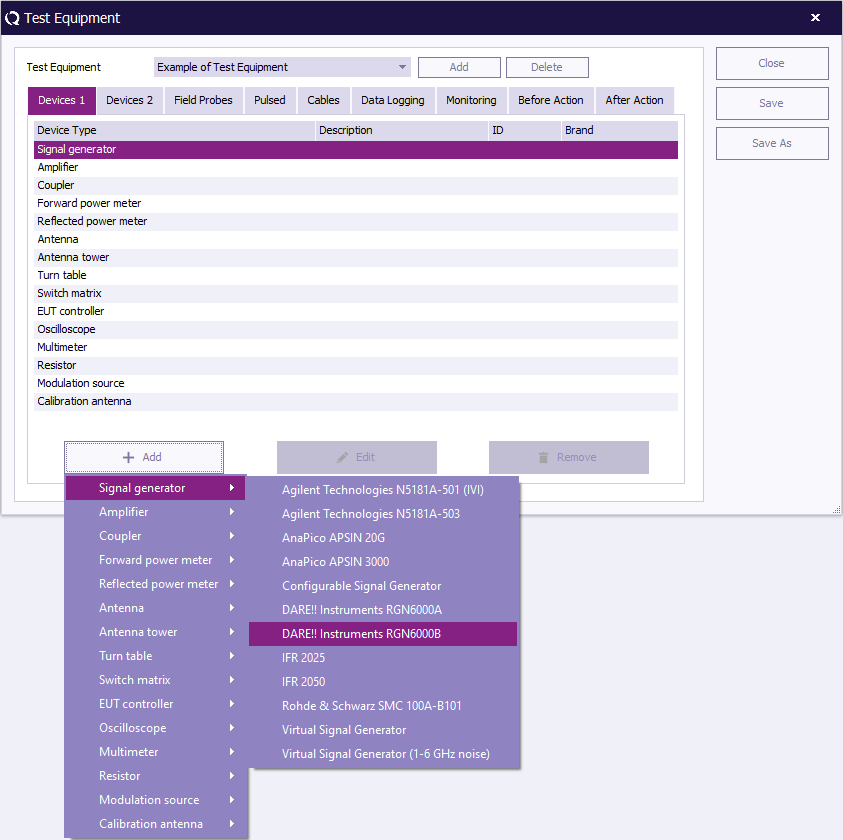
To | To add a device, click ''' 'Add' ''' (at the bottom left of the window), a menu will open below the button to show the available devices for each Device Type. | ||
Select and click on the desired device. The device will then appear in the equipment overview. | |||
[[Image:Test equipment add device 1.png]] | |||
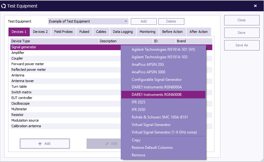
Another way to add a device is to click the desired '''Device Type''' in the 'Test Equipment' overview. | |||
A menu will open (at your mouse point) with the available devices for that Device Type. | |||
Select and click on the desired device. The device will then appear in the equipment overview. | |||
[[Image:Test equipment add device 2.png]] | |||
==== Editing devices ==== | |||
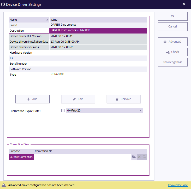
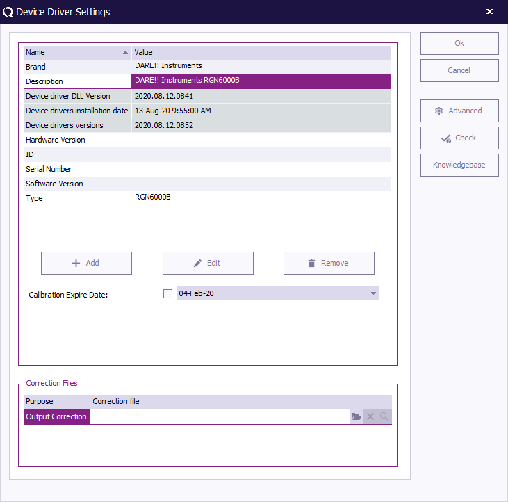
To edit a device, select the device and click ''' 'Edit' '''. The Device Driver Settings window will appear. | |||
Edit the settings as desired. To confirm your changes, click ''' 'OK' ''', to cancel your changes, click ''' 'Cancel' '''. You will be returned to the 'Test Equipment' window. | |||
[[Image:Test equipment device driver settings.png]] | |||
==== Removing devices ==== | |||
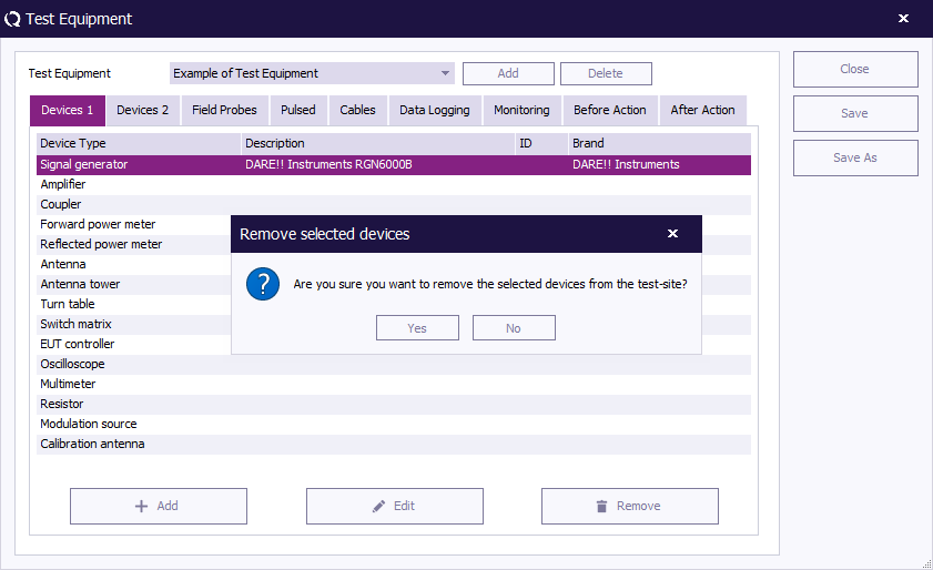
To remove a device, select the device and click ''' 'Remove' '''. A confirmation window will appear. | |||
Click 'Yes' to remove the device from the list, click ''' 'Cancel' ''' to cancel. You will be returned to the 'Test Equipment' window. | |||
[[Image:Test equipment remove selected devices.png]] | |||
=== | === Saving test equipment === | ||
To save the changes made in the test equipment list, click ''' 'Save' ''' (you will remain in the 'Test Equipment' window). | |||
==== Save As ==== | |||
To save the test equipment list under a new name, click ''' 'Save As' '''. | |||
Enter a new name for the test equipment in the ''' 'New Test Equipment' window''' (e.g. Example Test Equipment 2). | |||
Click ''' 'OK' ''' to confirm the name of the new test equipment, or click ''' 'Cancel' ''' to cancel the new name. You will be returned to the 'Test Equipment' window. | |||
[[Image:Test equipment save as.png]] | |||
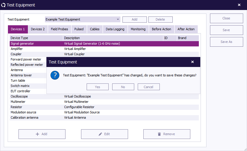
To close the 'Test Equipment' window, click ''' 'Close' '''. | |||
If you have not saved the changes to the test equipment list, a dedicated window will appear asking you to save these changes. | |||
To save the changes, click ''' 'Yes' ''', to not save the changes, click ''' 'No' '''. The 'Test Equipment' window will close. | |||
[[Image:Test equipment close.png]] | |||
== Before Actions & After Actions == | |||
The before and after actions of a testsite are designed to be triggered when the testsite is activated (before actions) or deactivated (after actions). | |||
These before and after actions can be seen as like switching relays to desired positions when a testsite is activated, and switching the relays to a default position again when the testsite is deactivated. | |||
When a testsite is used in two consecutive bands, the after and before actions are not executed, because there is no change in the activated testsite. | |||
When a test with 3 bands is configured, and the first and third band are using the same testsite, while another testsite is selected for the second band, then the after and before actions will be executed when the test is switching from band 1 to band 2, and again when the test is switching from band 2 to band 3. | |||
=== Before Action === | |||
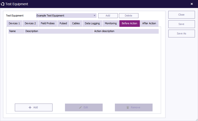
Under the tab 'Before Action' any and all actions that the end-user wants to have carried out before the equipment of the selected 'test equipment' is initialized can be specified. | |||
'Before actions' can be used to: | |||
* Turn on a manual controlled amplifier. | |||
* Manually change antenna height or polarization. | |||
* Connect cables or create a specific measurement setup. | |||
(It is also possible to specify actions that should be carried out after the equipment of the selected Test Equipment is disabled. This functionality is called 'After Action'.) | |||
The easiest way to explain this function is with an example: | |||
==== Example ==== | |||
{{RadiMation}} needs to be configured for people who do not perform EMC measurements every day. To make sure the engineers do not forget to use the right equipment and procedure, the manager has decided to incorporate a reminder in the test setup. | |||
This is done by adding a message in the 'Before Action' configuration: | |||
1. Open the 'Test Equipment' window, select the desired test equipment set and open the ''' 'Before Action' tab'''. | |||
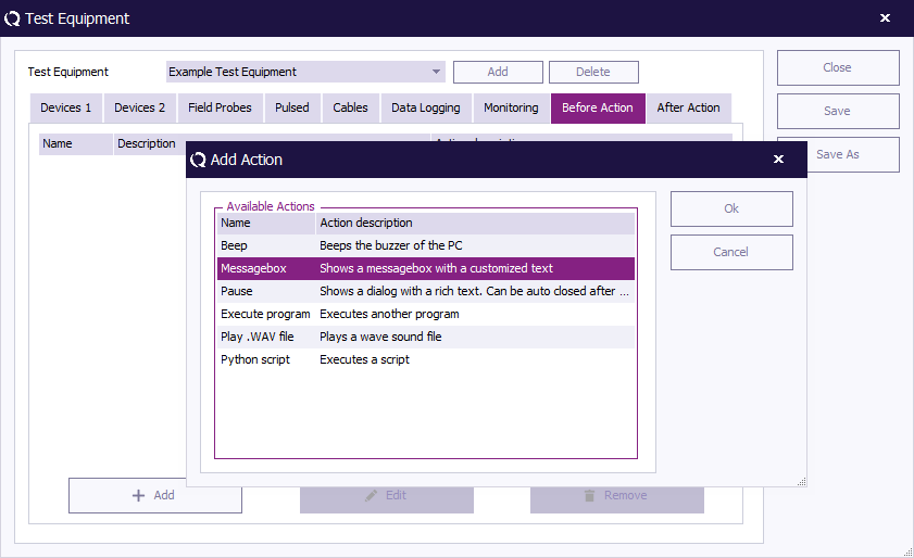
2. Press the ''' 'Add' ''' button at the bottom left of the 'Before Action' tab to open the 'Add Action' window. | |||
[[IMAGE:AddAction_BeforeActions.PNG]] | |||
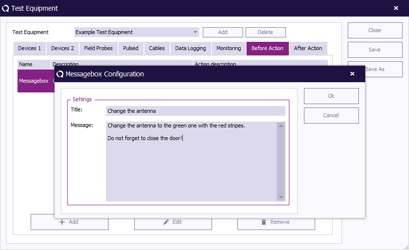
3. Select the ''' 'Messagebox' option''' and click ''' 'OK' '''(or double click on the 'Messagebox' option). A dedicated window will appear. | |||
[[IMAGE:AddAction_1.PNG]] | |||
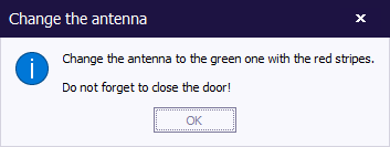
4. Configuring the desired text in the 'Messagebox Configuration' window and click ''' 'OK' '''. You will be returned to the 'Test Equipment' window. | |||
[[IMAGE:AddAction_MessageBox.PNG]] | |||
The message has now been added to the configuration. As a result, {{RadiMation}} will prompt the following message before the test equipment is initialized: | |||
[[IMAGE:AddACtion_PopUp.PNG]] | |||
=== After Action === | |||
Under the tab 'After Action' any and all actions that the end-user wants to have carried out after the equipment of the selected 'test equipment' is disabled can be specified. | |||
'After actions' can be used to: | |||
* Manually turn off the amplifier. | |||
* Play a Wav file (as an auditory signal) to alert the user that the measurement is done. | |||
(It is also possible to specify actions that should be carried out before the equipment of the selected Test Equipment is initialized. This functionality is called 'Before Action'.) | |||
== Default address information == | |||
When a new [[EUT]] file is created, the name and address information of the client, manufacturer and test site can be entered. | |||
In many situations one or more of those address information will be the same for different [[EUT]] files (for example, when a test site use {{RadiMation}}, the test site address information will always be the same). | |||
To prevent users from having to enter repetitive data input, {{RadiMation}} provides the possibility to set default address information for: | |||
* the client that has ordered that tests should be performed on the EUT | |||
* the manufacturer that has produced the EUT | |||
* the test site that is performing the tests on the EUT | |||
Address information entered on the {{WindowTitle|Default Address Information}} window, will be automatically included on the {{WindowTitle|EUT}} window and therefore only needs to be entered once. | |||
To add, modify or delete the default address information, use the menu: | |||
{{Menu|Configuration|Default Address Information}} | |||
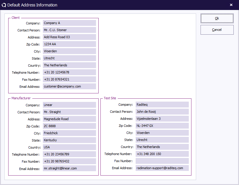
In the {{WindowTitle|Default Address Information}} window, the default address information can be configured. Specifying this information is not required, however it has the benefit that address information that is always the same doesn't need to be entered over and over again in every new [[EUT]] file. | |||
[[Image:Default Address Information.png]] | |||
{{ScreenElementDescriptionStart}} | |||
{{ScreenElementDescription|Client Company|The default company name for the client.}} | |||
{{ScreenElementDescription|Client Contact Person|The default contact person for the client.}} | |||
{{ScreenElementDescription|Client Address|The default address for the client.}} | |||
{{ScreenElementDescription|Client Zip Code|The default zip code for the client.}} | |||
{{ScreenElementDescription|Client City|The default city for the client.}} | |||
{{ScreenElementDescription|Client State|The default state for the client.}} | |||
{{ScreenElementDescription|Client Country|The default country for the client.}} | |||
{{ScreenElementDescription|Client Telephone Number|The default telephone number for the client.}} | |||
{{ScreenElementDescription|Client Fax Number|The default fax numberfor the client.}} | |||
{{ScreenElementDescription|Client Email Address|The default e-mail address for the client.}} | |||
{{ScreenElementDescription|Manufacturer Company|The default company name for the manufacturer.}} | |||
{{ScreenElementDescription|Manufacturer Contact Person|The default contact person for the manufacturer.}} | |||
{{ScreenElementDescription|Manufacturer Address|The default address for the manufacturer.}} | |||
{{ScreenElementDescription|Manufacturer Zip Code|The default zip code for the manufacturer.}} | |||
{{ScreenElementDescription|Manufacturer City|The default city for the manufacturer.}} | |||
{{ScreenElementDescription|Manufacturer State|The default state for the manufacturer.}} | |||
{{ScreenElementDescription|Manufacturer Country|The default country for the manufacturer.}} | |||
{{ScreenElementDescription|Manufacturer Telephone Number|The default telephone number for the manufacturer.}} | |||
{{ScreenElementDescription|Manufacturer Fax Number|The default fax number for the manufacturer.}} | |||
{{ScreenElementDescription|Manufacturer Email Address|The default e-mail address for the manufacturer.}} | |||
{{ScreenElementDescription|Test Site Company|The default company name for the test site.}} | |||
{{ScreenElementDescription|Test Site Contact Person|The default contact person for the test site.}} | |||
{{ScreenElementDescription|Test Site Address|The default address for the test site.}} | |||
{{ScreenElementDescription|Test Site Zip Code|The default zip code for the test site.}} | |||
{{ScreenElementDescription|Test Site City|The default city for the test site.}} | |||
{{ScreenElementDescription|Test Site State|The default state for the test site.}} | |||
{{ScreenElementDescription|Test Site Country|The default country for the test site.}} | |||
{{ScreenElementDescription|Test Site Telephone Number|The default telephone number for the test site.}} | |||
{{ScreenElementDescription|Test Site Fax Number|The default fax number for the test site.}} | |||
{{ScreenElementDescription|Test Site Email Address|The default e-mail address for the test site.}} | |||
{{ScreenElementDescription|Ok|Stores the modified information and closes the window.}} | |||
{{ScreenElementDescription|Cancel|Discards the modified information and closes the window.}} | |||
{{ScreenElementDescriptionEnd}} | |||
The default address information is stored in the {{ScreenElement|Device Driver Configuration Files}} directory, which can be configured in the global {{RadiMation}} configuration. | |||
== Advanced options == | |||
[[Image:Configuration pull down menu.png]] | |||
There are a several [[advanced options]] in {{RadiMation}}, that allow to tune or optimize some specific settings. Making changes to one or more of those settings, can have a major influence in the correct functioning of the software. Changes to one or more of these advanced options are only needed to circumvent a specific situation. Before changes can be made, a specific password should be specified. The required password is not related to any of the passwords of existing engineers. If it is necessary to make a change to one or more of the advanced options, the password will be provided to the end-user by the [[reseller]] or {{CompanyName}} If the password is specified correctly, a configuration window is shown that includes a table to review and edit the list of advanced options. | |||
== Configuration == | |||
{{RadiMation}} allows the user to define an extensive default configuration. This includes the settings for the: | |||
# Units | |||
# Directories | |||
# Device Drivers | |||
# Graphs | |||
# Database | |||
# Language | |||
# Measurement settings | |||
# Product standards | |||
# Basic standards | |||
# Enhanced Status Window | |||
Each of these settings are available on a specific tab in the global configuration which can be accessed through the menu: | |||
{{Menu|Configuration|Configuration}} | |||
[[Image:Config configuration.png]] | |||
=== 1. Units configuration === | |||
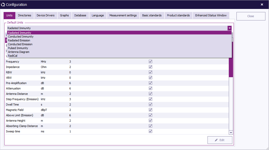
The default settings for the different units can be set in the ''' 'Units' tab'''. These units are used throughout the software package and can be changed at any time during measurements and viewing. | |||
It is possible to define different units for different tests. The following can be selected: | |||
* Radiated Immunity | |||
* Conducted Immunity | |||
* Radiated Emission | |||
* Conducted Emission | |||
* Pulsed Immunity | |||
* Antenna Diagram | |||
* RadiCal | |||
==== Changing unit settings ==== | |||
To change the settings of a unit, choose the desired test (e.g. Radiated Immunity) from the drop down menu in the ''' 'Units' tab'''. | |||
[[Image:Configuration units test selection.png]] | |||
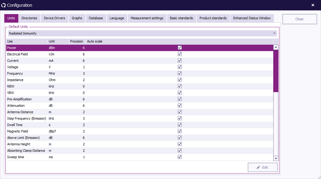
Select the measurement (e.g. Power) and click ''' 'Change' '''. | |||
[[Image:Configuration Units.png]] | |||
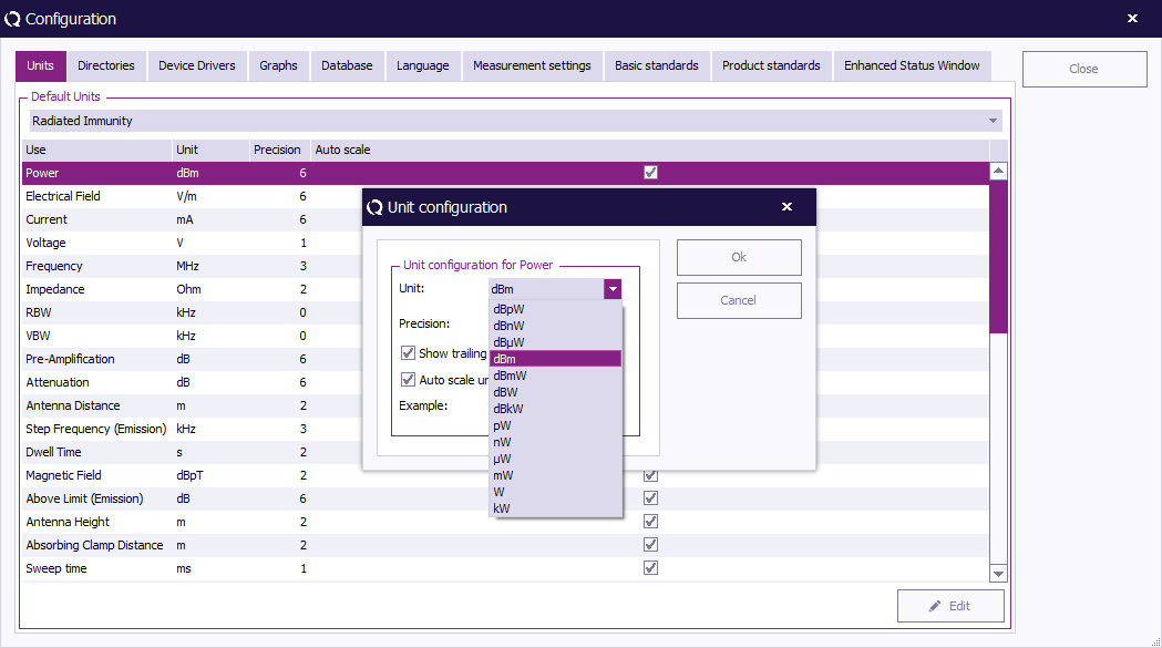
The ''' '{{WindowTitle|Unit configuration}}' window''' will appear, allowing you to change the parameters of the unit. | |||
To confirm your changes, click ''' 'OK' ''', to cancel your changes, click ''' 'Cancel' '''. You will be returned to the 'Configuration' window. | |||
[[Image:Configuration units change2.png]] | |||
Click ''' 'Close' ''' to leave the 'Configuration' window. | |||
=== 2. Directories configuration === | |||
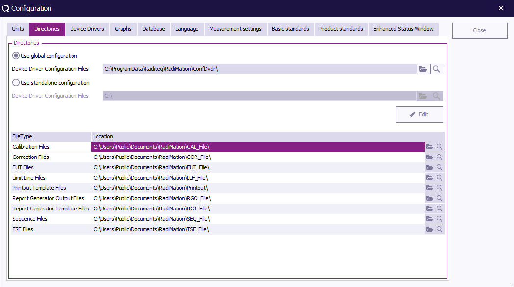
The {{RadiMation}} software can use different directories to store different files. | |||
The location of the Device Driver Configuration Files can be specified: | |||
* Device Driver Configuration Files (CONFDVDR), | |||
The location of the following data file types can be specified: | |||
* Equipment Under Test Data files (*.EUT files), | |||
* Correction files (*.COR files) | |||
* Calibration files (*.CAL files), | |||
* Configuration files (*.TSF files), | |||
* Sequence files (*.SEQ files), | |||
* Limit line files (*.LLF files). | |||
* Printout files (*.DOC files). | |||
The different file types are described in [[Chapter 18|Chapter 18 “{{RadiMation}} file types and locations”]]. | |||
For each data type the default location can be entered through the configuration. The path name can link to a directory on a local or on a shared network drive. Selecting a network location will allow you to store data (e.g. EUT data) on a computer network, making it more accessible. This will allow you to configure {{RadiMation}}, to make use of a networked configuration with multiple test PC's, sharing the same configuration. | |||
==== Open the 'Directories' configuration screen ==== | |||
Open the directory configuration by selecting from the menu: | |||
{{Menu|Configuration|Configuration}} | |||
[[Image:Config configuration.png]] | |||
Go to the {{ScreenElement|Directories}} tab. | |||
[[Image:Configuration Directories.png]] | |||
==== Modifying the 'Device Driver Configuration Files' directory ==== | |||
With the {{ScreenElement|Use Global Configuration}} option, it is possible to share the configuration with other versions of RadiMation on the same computer. This is the default setting. | |||
With the {{ScreenElement|Use standalone configuration}} option, it is possible to create an version specific isolated configuration directory with it's own content only used for this version of RadiMation. This can for example be used to verify and validate another {{RadiMation}} version without influencing another {{RadiMation}} version. | |||
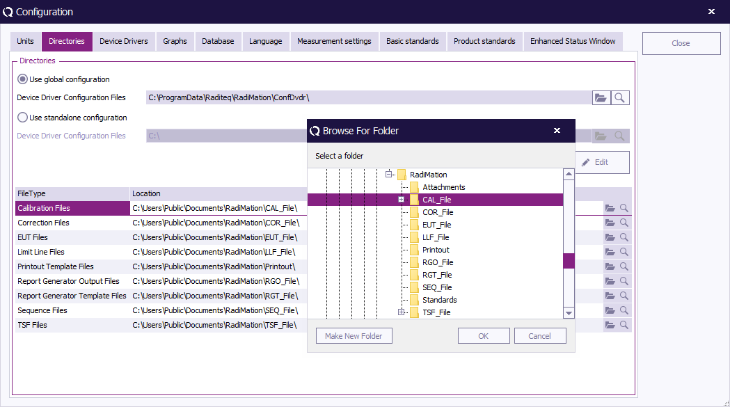
The location of the {{ScreenElement|Device Driver Configuration Files}} can by changed by clicking on the {{ScreenElement|'Open Folder' icon}}. A ''' 'Browse For Folder' ''' window will appear, allowing to select an existing device driver configuration files directory. If an empty or an invalid device driver configuration files directory is selected, an error will be shown, and the original selected directory will remain selected. | |||
==== Creating a new 'Device Driver Configuration Files' folder ==== | |||
When it's needed to create a new {{ScreenElement|Device Driver Configuration Files}} folder, click {{ScreenElement|Edit}} and select {{ScreenElement|Create and set new folder}}. A directory chooser will be prompted to create and / or select a new empty folder. The selected folder should be completely empty otherwise it cannot be initialized to become a {{ScreenElement|Device Driver Configuration Files}} directory. | |||
==== Duplicating a 'Device Driver Configuration Files' folder ==== | |||
It is possible to duplicate an existing configuration folder, by clicking on {{ScreenElement|Edit}} and either choose {{ScreenElement|Duplicate and set from current global folder}} or {{ScreenElement|Duplicate and set from current standalone folder}}. A directory chooser will be prompted to create and / or select a new empty folder to copy the content of the source configuration to. After the duplication of the folder, the new {{ScreenElement|Device Driver Configuration Files}} directory will be selected. | |||
==== Change the path for a file type ==== | |||
Select the directory that you wish to change and click on the {{ScreenElement|Open Folder}} icon to select a different directory. | |||
[[Image:Configuration Directories.png]] | |||
The {{ScreenElement|Browse For Folder}} window will appear, allowing you to select (or make) a new folder in your directory. | |||
To confirm your change, click {{ScreenElement|Select folder}}, or to cancel your change, click {{ScreenElement|Cancel}}. You will be returned to the {{ScreenElement|Configuration}} window. | |||
[[Image:Browse Calibration File Directory.png]] | |||
Click {{ScreenElement|Close}} to leave the {{ScreenElement|Configuration}} window. | |||
=== 3. Device Driver configuration === | |||
Device drivers let your software know which equipment has to be used and controlled during EMC tests. In {{RadiMation}}, these device drivers only need to be configured to the customer requirements once. During the configuration of the device driver, information such as the IEEE address or RS232 COM-port has to be entered. | |||
You can configure the device drivers in the ''' 'Device Drivers' tab''' of the ''' 'Configuration' window'''. | |||
This window can be accessed in one of two ways: | |||
1. Through the 'Configuration' tab. | |||
[[Image:Config configuration.png]] | |||
2. Through the 'Devices' tab. | |||
[[Image:Device configure.png]] | |||
==== Select a device driver type ==== | |||
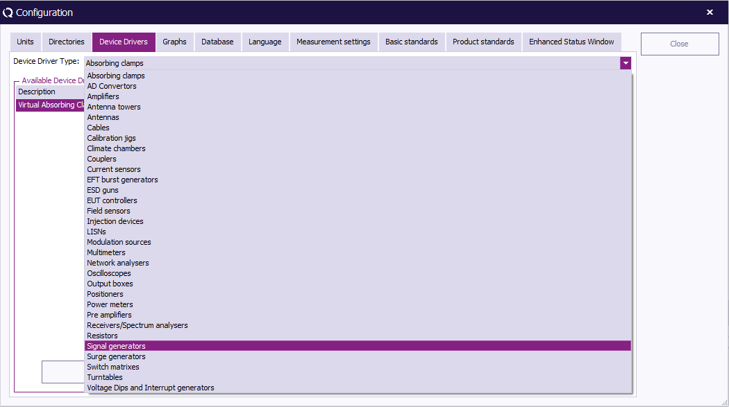
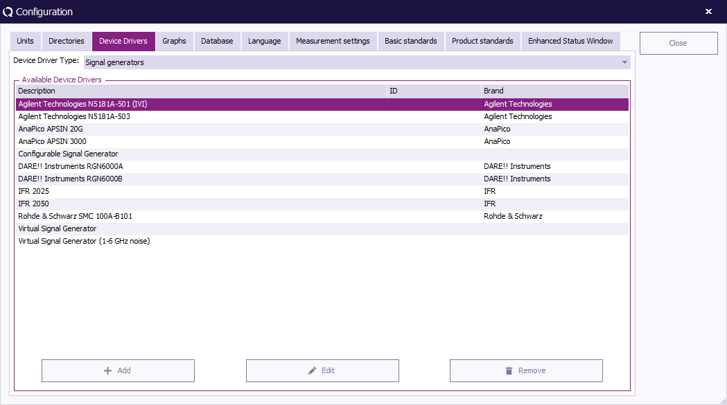
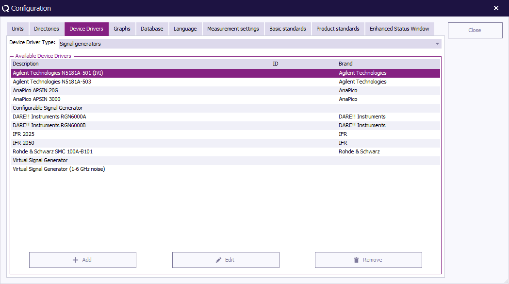
The first step to create or configure a device driver is to select the required ''' '[[Device Types|Device Driver Type]]' ''' (e.g. Signal Generator). This can be done from the drop-down menu in the ‘Configuration’ window. One’s a type has been selected, the available drivers for that type will be shown. | |||
[[Image:Device driver type.png]] | |||
==== Adding a new device driver ==== | |||
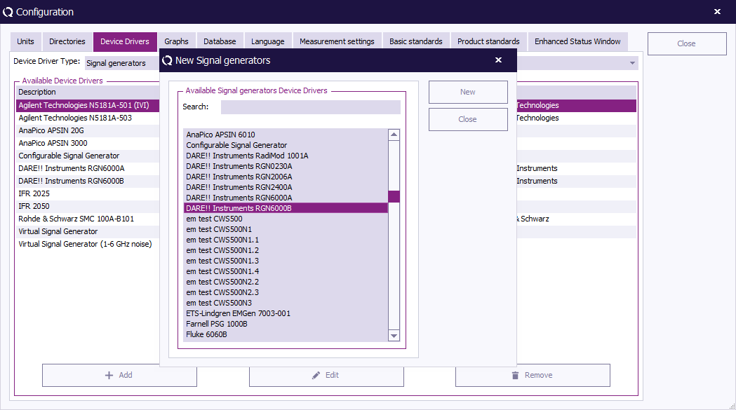
To create a new {{RadiMation}} device driver, select the desired ''' 'Device Driver Type' ''' (e.g. Signal Generator) and click ''' 'Add' '''. A dedicated window will appear. | |||
[[Image:Device driver add.png]] | |||
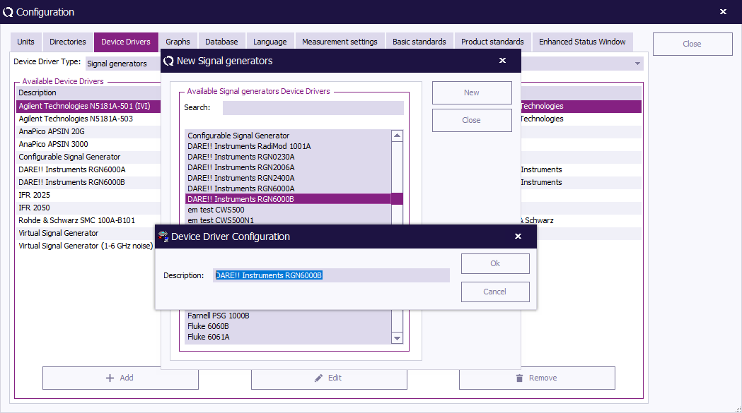
Select a new device driver (in the scroll menu or through the search function) in the new window and click ''' 'New' '''. The 'Device Driver Configuration' will appear. | |||
To cancel your selection and return to the 'Configuration' window, click ''' 'Close' '''. | |||
[[Image:New signal generators.png]] | |||
In the ''' 'Device Driver Configuration' window''' the name/description of the chosen device driver can be changed. | |||
To confirm your changes (or the provided description), click ''' 'OK' ''', the 'Device Driver Settings' window will appear. This window will allow you to edit the information on this device driver. More information about editing device driver settings (and this window) is available further below. | |||
To cancel your changes, click ''' 'Cancel' '''. You will be returned to the previous window (e.g. New Signal generators). | |||
[[Image:Device driver configuration.png]] | |||
==== Editing a device driver ==== | |||
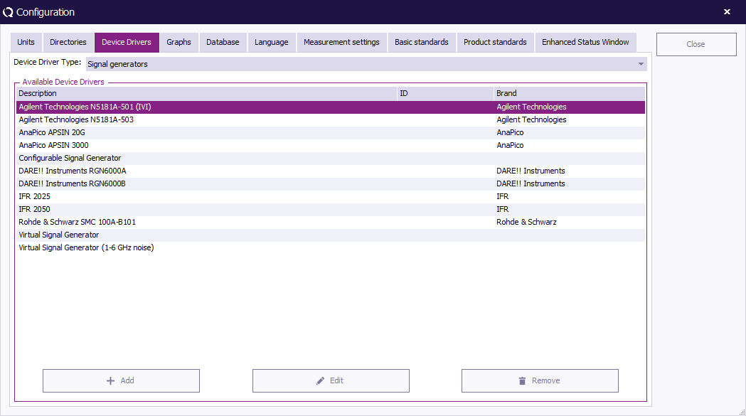
To edit an existing device driver, select the desired (device driver) type and device driver, then click ''' 'Edit' '''. The 'Device Driver Settings' window will appear. More information about this window is available further below. | |||
[[Image:Device driver edit.png]] | |||
==== Removing a device driver ==== | |||
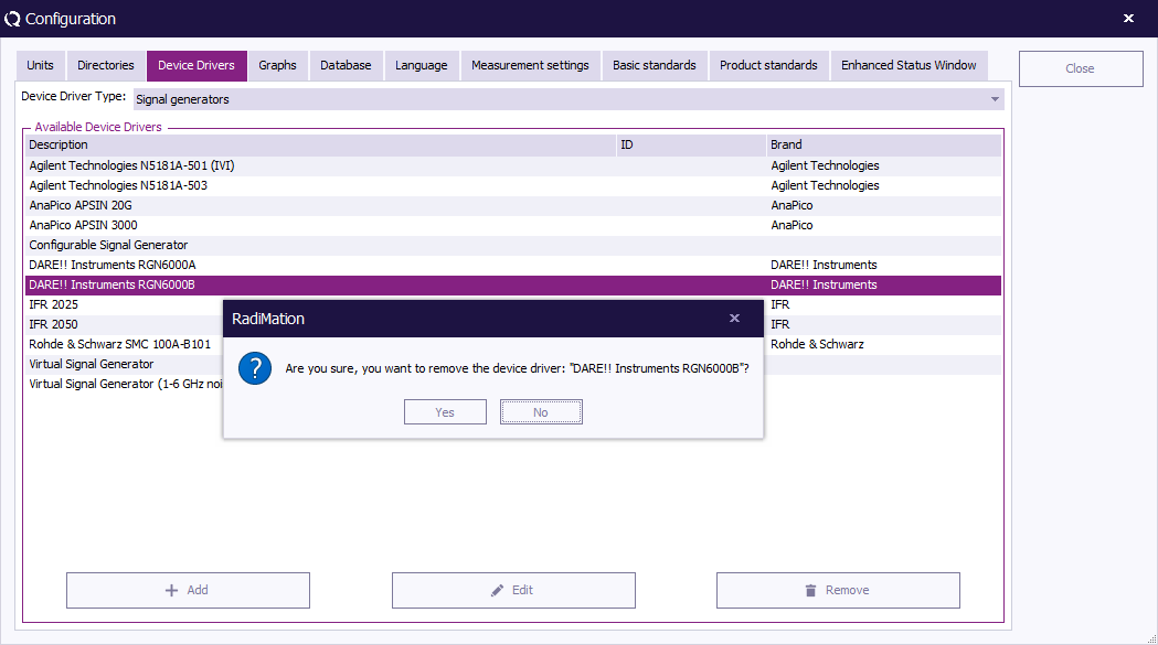
To remove an existing device driver, select the desired (device driver) type and device driver, then click ''' 'Remove' '''. | |||
[[Image:Device driver remove.png]] | |||
A confirmation window will appear. To remove the selected device driver, click ''' 'Yes' ''', to cancel, click ''' 'No' '''. You will be returned to the 'Configuration' window. | |||
[[Image:Device driver remove2.png]] | |||
=== Device Driver Settings === | |||
The 'Device Driver Settings' window contains information on the selected device driver. In this window the generic settings for that driver can be added, edited and removed. | |||
==== Confirm settings ==== | |||
To confirm the (current/new) settings, click ''' 'OK' '''. To cancel changes made during editing, click ''' 'Cancel' '''. You will be returned to the 'Configuration' window. | |||
[[Image:Device driver settings.png]] | |||
==== Fixed information ==== | |||
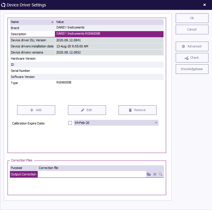
The 'Device Driver Settings' window contains a minimum list of 'fixed information'. Although these settings cannot be removed, part of their information can be altered. These settings include: | |||
{{ScreenElementDescriptionStart}} | |||
{{ScreenElementDescription|Brand|Shows the brand of the device. This information can be changed/viewed in this cell and can be used in the report generator.}} | |||
{{ScreenElementDescription|Description|Shows the description of the device. This information can be changed/viewed in this cell and can be used in the report generator. Changing the description does not result in losing the device in the test sites. The description is automatically updated in the test site information. If a report is generated from a test done prior to the description change the old description will be inserted.}} | |||
{{ScreenElementDescription|Device driver DLL Version|Shows the exact version of the DLL in which the device driver is contained. This is a unique identifier that specifies the version of the device driver. The contents of this cell cannot be changed. (More information on this data cell is explained further below in the paragraph ‘Storing the driver version in the test file’.)}} | |||
{{ScreenElementDescription|Device drivers installation date|Shows the date and time of the last update/installation of the device drivers. The contents of this cell cannot be changed. (More information on this data cell is explained further below in the paragraph ‘Storing the driver version in the test file’.)}} | |||
{{ScreenElementDescription|Device drivers versions|Shows the version number of the last update/installation of the device drivers. The contents of this cell cannot be changed. (More information on this data cell is explained further below in the paragraph ‘Storing the driver version in the test file’.)}} | |||
{{ScreenElementDescription|Hardware version|Shows the hardware version of the device. This information can be changed/viewed in this cell and can be used in the report generator.}} | |||
{{ScreenElementDescription|ID|Shows the internally used ID of the device. This information can be changed/viewed in this cell and can be used in the report generator. The main function of this window is to link your measurement to your devices for easier reproduction.}} | |||
{{ScreenElementDescription|Serial number|Shows the serial number of the device. This information can be changed/viewed in this cell and can be used in the report generator.}} | |||
{{ScreenElementDescription|Software version|Shows the software version of the device. This information can be changed/viewed in this cell and can be used in the report generator.}} | |||
{{ScreenElementDescription|Type|Shows the type of the device. This information can be changed/viewed in this cell and can be used in the report generator.}} | |||
{{ScreenElementDescriptionEnd}} | |||
==== Additional options ==== | |||
The 'Device Driver Settings' window provides additional options besides changing/viewing the 'fixed information', such as: | |||
{{ScreenElementDescriptionStart}} | |||
{{ScreenElementDescription|Add|The ‘’’ ‘Add’ button’’’ can be used to add additional information items to the general device driver settings. The additional items will be shown in the list. Additional information items can be used to note the storage location, the location of the user manual, etc.}} | |||
{{ScreenElementDescription|Edit|The ‘’’ ‘Edit’ button’’’ can be used to edit the information of a selected item. Information items that cannot be modified cannot be edited.}} | |||
{{ScreenElementDescription|Remove|The ‘’’ ‘Remove’ button’’’ can be used to remove a selected information item from the list. Only additional information items can be removed. Fixed information items, as described previously, cannot be removed.}} | |||
{{ScreenElementDescription|Zero Interval|When the {{ScreenElement|Zero interval}} is activated, it is possible to specify a time period in minutes, in which a device does not need to be ‘re-zero-ed’. For accurate measurements it is necessary that [[Power Meter]]s and [[Field Sensor]]s are zero-ed. A zero operation generally takes several seconds to be completed and it may be valid for a few hours. To prevent that a device is ‘re-zero-ed’ during each test initialization, it is possible to set a zero interval in minutes. When a test is initialized and the device is already zero-ed within the specified zero interval, no zero will be performed at that time. Specifying and activating the zero interval can be a significantly reduce the time that is needed to initialize each test. | |||
This setting is only available for power meter and field strength sensor devices.}} | |||
{{ScreenElementDescription|Calibration Expire Date|This field can be used to set the date on which the device needs to be re-calibrated. Depending upon the setting in the configuration window, {{Radimation}} will use this date to give warnings/notifications on the recalibration. When you press the ‘calendar icon’ to the right of this field a small window will appear, allowing you to select the new date.}} | |||
{{ScreenElementDescription|Advanced|The ‘’’ ‘Advanced’ button’’’ can be used to open the advanced menu of the device driver. In chapter 15, the paragraph ‘Device specific configuration’ will explain this menu for every device type. Please note that the configuration does not apply on the configurable or virtual drivers. Please view the paragraphs about ‘Configurable devices’ or ‘Virtual devices’ (also in chapter 15) for these devices.}} | |||
{{ScreenElementDescription|Check|The ‘’’ ‘Check’ button’’’ can be used to check if the device is connected. This check is the same as the check that is performed during each test initialization. This check can be used to determine if the correct addressing is set, and whether communication with the device is possible. (This option is explained further below in the paragraph ‘Checking the device connection’.)}} | |||
{{ScreenElementDescription|Knowledgebase|The ‘’’ ‘Knowledgebase’ button’’’ can be used to open a new web-browser window which will show the [[RadiWiki]] page about that device driver. That [[RadiWiki]] page can contain additional information or a detailed explanation of all the advanced settings.}} | |||
{{ScreenElementDescriptionEnd}} | |||
==== Checking the device connection ==== | |||
The 'Device Driver Settings' window contains a 'Check' button that can be used to check whether the device driver is correctly connected to the PC. | |||
[[Image:RadiMationDeviceDriverSettings.png]] | |||
When the 'Check' button is clicked, the following actions are performed: | |||
=== | # RadiMation tries to load the DLL of the device driver | ||
# RadiMation tries to create an instance of the device driver | |||
# The settings (as configured under 'Advanced') are loaded | |||
# The device driver is instructed to check if the (hardware) device itself is working correctly | |||
# The device driver instance is removed from memory again | |||
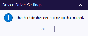
If one of these steps is unsuccessful, an error message will be shown. If all the steps are successful, a message will be shown that the device connected has passed the check. (See the image below.) | |||
[[Image:RadiMationSuccesfullDeviceDriverCheck.png]] | |||
This is a very helpful tool because it is a fast method to check whether the advanced settings (especially the ([[GPIB]]) address) of the device are set correctly. If this 'Check' is successful, the 'device check' during the test initialization (which performs the same check) will also be successful. | |||
The check that is performed depends on the implemented device driver. For example, some devices (like antenna's, couplers, LISN's, injection clamps, etc.) cannot be checked for the correct connection to the PC (done at step 4), because there is no connection at all. In addition, some device drivers assume that the laser of the device is activated before the check is successful. Despite these deviations, the 'Check' functionality will still work and show the message displayed above, as long as the device driver passes the (appropriate) check. | |||
==== Storing the driver version in the test file ==== | |||
For quality accreditation reasons it is necessary to store the version numbers of the hardware, firmware and software of the equipment used to perform EMC measurements. {{RadiMation}} uses device drivers to control this equipment. Because these device drivers greatly influence the overall (and correct) functioning of the EMC measurement, it is important that the version of these device driver is stored together with the measurements results of each test. | |||
{{RadiMation}} can store all this information, most of which is also automatically determined by the program itself. This information (including the device driver version) is shown in the 'Device Driver Settings' window. (As explained further above in the paragraph 'Fixed information'.) | |||
About the device driver information: | |||
The numbers of the device drivers system and/or the used .dll version number of a specific device are always (slightly) different by default. An example situation is included below. | |||
* The value of the ''' 'Device driver DLL Version' ''' shows the date and time on which this specific .dll was compiled. (For example: 2013.07.11.1405. The date of the used .dll for this specific device is June 11, 2013 at 14:05 pm.) | |||
* The value of the ''' 'Device drivers installation date' ''' shows when the device driver setup was installed by the end-user for the specific version of RadiMation that is currently running. (For example: 12.07.2013 08:37:00. The install date is June 12, 2013 at 08:37 am.) | |||
* The value of the ''' 'Device drivers versions' ''' shows which device driver version you are currently running. This is the date and time when all the device driver DLL's are packaged into the DRIVERS.EXE. (For example: 2013.07.11.1414. The date of the device drivers system is June 11, 2013 at 14:14 pm.) | |||
Now we can conclude that: | |||
* The Device Drivers version that is being used is 2013.07.11.1414 | |||
* The used .dll version of this specific device is 2013.07.11.1405 | |||
* The latest device drivers setup is installed on June 12, 2013 at 08:37 am. | |||
It happens very often that a Device driver DLL is modified multiple times in a day. By including the time in the version number it is possible to determine exactly which DLL version is used. It is also possible that (in specific situations) a DLL is provided without using an updated DRIVERS.EXE package. In that situation the 'Device driver DLL Version' can be newer than the 'Device drivers versions'. | |||
=== 4. Graphs configuration === | |||
{{RadiMation}} allows you to customize the way graphics are displayed on your screen. | |||
To configure the style of the shown graphs, go to the ''' 'Configuration' window''' in the ''' 'Configuration' tab'''. | |||
[[Image:Config configuration.png]] | |||
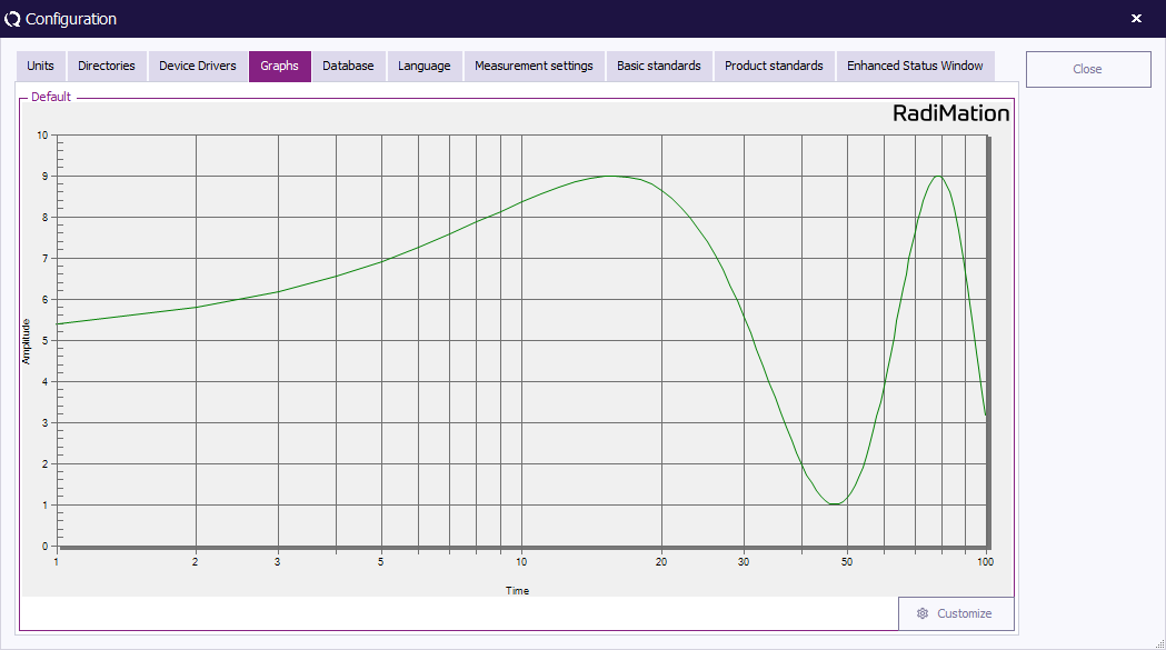
An example graph is shown in the ''' 'Graphs' tab''' that is created with the current settings. To change these graph settings, click ''' 'Customize' '''. | |||
[[Image:Configuration Graphs.png]] | |||
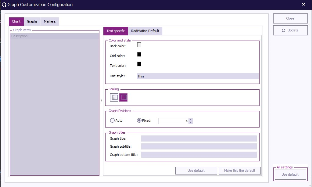
The '{{WindowTitle|Graph Customization Configuration}}' '''window''' contains three tabs; ''' 'Chart' ''', ''' 'Graph' ''' and ''' 'Markings' '''. | |||
The ''' 'Chart' tab''' contains the settings related to the overall graph and can be used to determine the colors, layout and titles. | |||
The | The ''' 'Graph' tab''' contains the settings related to the graph lines shown in the graph and can be used to determine the colors, scaling and layout of each and every shown graph line. | ||
The ''' 'Markers' tab''' contains the settings related to the markers on the graph and can be used to determine the colors, style and scaling of each and every shown marker. | |||
[[Image:GraphCustomization Chart.png]] | |||
To change the graph settings, select a graph (component) in the left section of the window, then make the desired changes in the right section of the window. | |||
Click ''' 'Update' ''' to update the graph settings without closing the '{{WindowTitle|Graph Customization Configuration}}' '''window'''. This will allow you to see the effect of the new settings and make additional changes. | |||
===Measurement Settings=== | Click ''' 'Close' ''' to update (and save) the graph settings and close the '{{WindowTitle|Graph Customization Configuration}}' '''window'''. You will be returned to the ''' 'Configuration' window'''. | ||
The selected settings in the '{{WindowTitle|Graph Customization Configuration}}' '''window''' are used as the {{RadiMation}} default settings. It is still possible to overrule these settings for individual tests to more specific settings. | |||
Click ''' 'Restore factory default' ''' to return to the factory settings. | |||
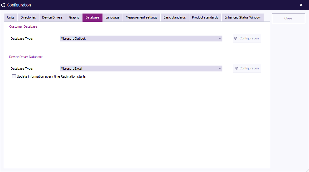
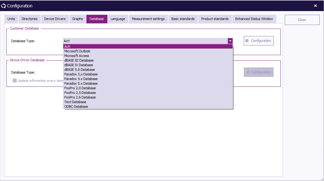
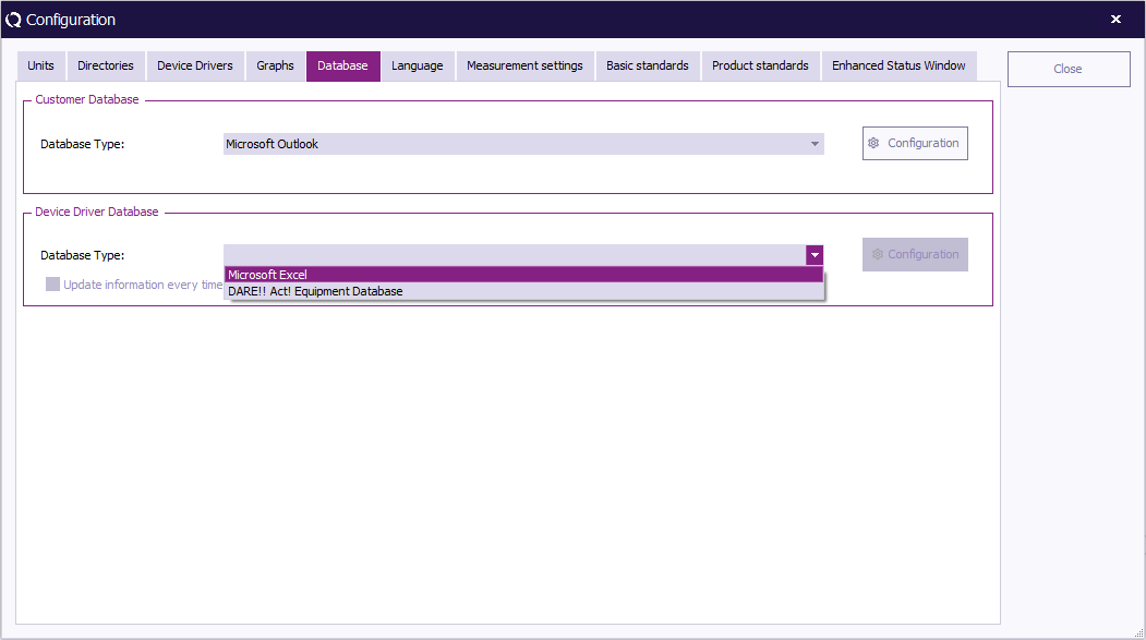
=== 5. Database configuration === | |||
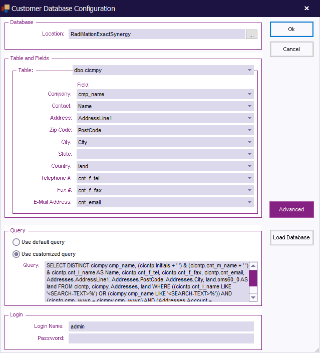
{{:Customer database}} | |||
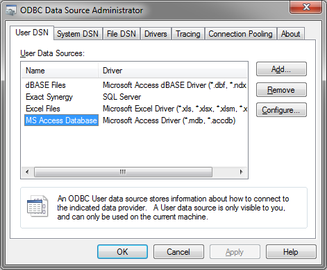
===Additional Setup for ODBC Connected databases === | |||
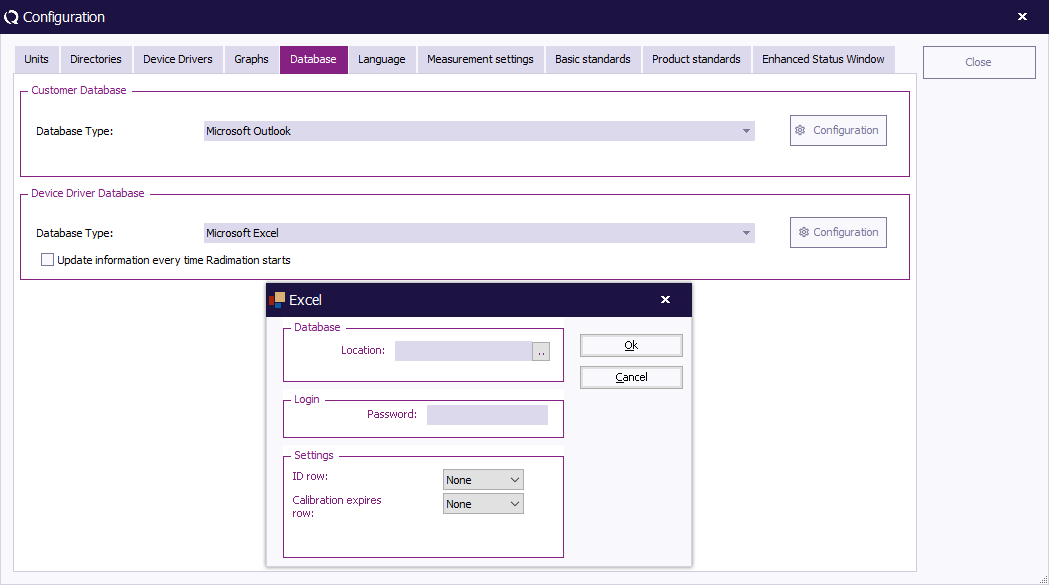
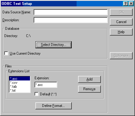
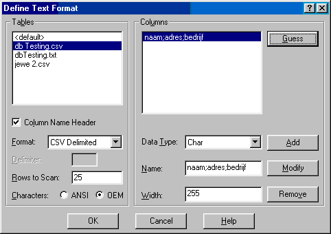
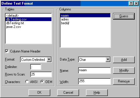
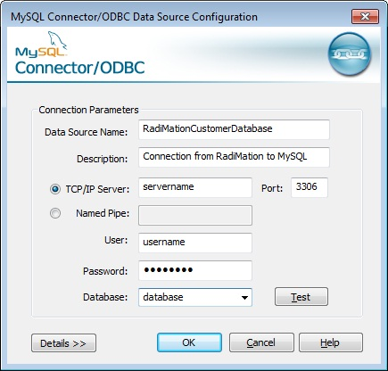
Text, CSV, Excel, [[MSSQL]] and [[MySQL]] dabase files need some additional setup before they can be used. The reason for this is that {{RadiMation}} uses [[ODBC]] to connect and read out thoes databases. This additional setup of an [[ODBC]] connection must be performed before the database driver can be configured in {{RadimationLink}}. {{:ODBC Configuration}} | |||
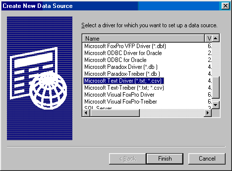
====ODBC text and CSV database files==== | |||
If the {{ScreenElement|Microsoft Text Driver (*.txt,*.csv)}} is selected, it will show the {{WindowTitle|ODBC text setup}} dialog. | |||
{{:ODBC text setup}} | |||
====MySQL ODBC database ==== | |||
If the {{ScreenElement|MySQL ODBC Driver}} is selected, it will show the {{WindowTitle|MySQL Connector/ODBC Data Source Configuration}} dialog. | |||
{{:MySQL Connector/ODBC Data Source Configuration}} | |||
====MSSQL ODBC database ==== | |||
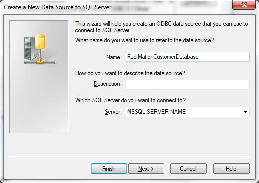
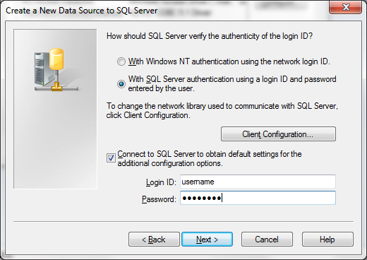
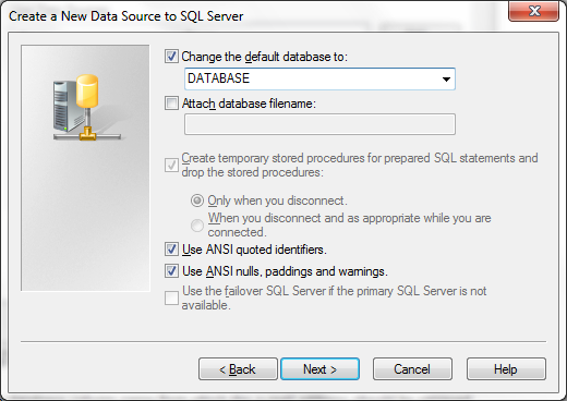
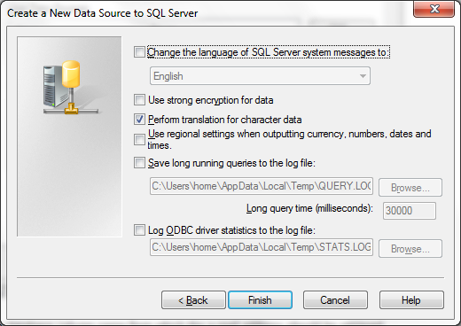
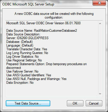
If the {{ScreenElement|SQL Server}} driver is selected, it will show the {{WindowTitle|SQL Server ODBC Driver Configuration}} dialog. | |||
{{:SQL Server ODBC Driver Configuration}} | |||
=== 6. Language Selection === | |||
{{RadiMation}} supports multi-language use. This means that the software package can be operated in several language. | |||
In addition, the multi- language support allows for easy translation from English to most other languages. | |||
Please contact your local reseller for the availability of your required language driver. | |||
The default language of {{RadiMation}} is UK English. | |||
To change the language settings, go to the ''' 'Configuration' window''' in the ''' 'Configuration' tab'''. | |||
[[Image:Config configuration.png]] | |||
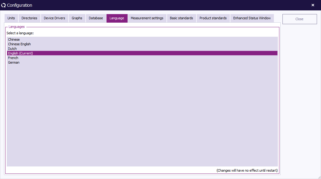
Go to the ''' 'Language' tab'''. The current language setting is marked with the text '''(current)'''. | |||
[[Image:Configuration Language.png]] | |||
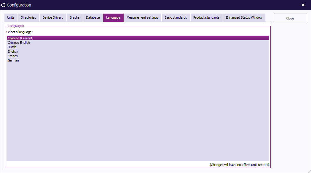
To change the language setting, select one of the other languages, click ''' 'Close' ''' (to leave the ''' 'Configuration' window''') and restart {{RadiMation}}. | |||
The selected language will only be active after {{RadiMation}} is restarted. | |||
[[Image:Configuration language2.png]] | |||
=== 7. Measurement Settings=== | |||
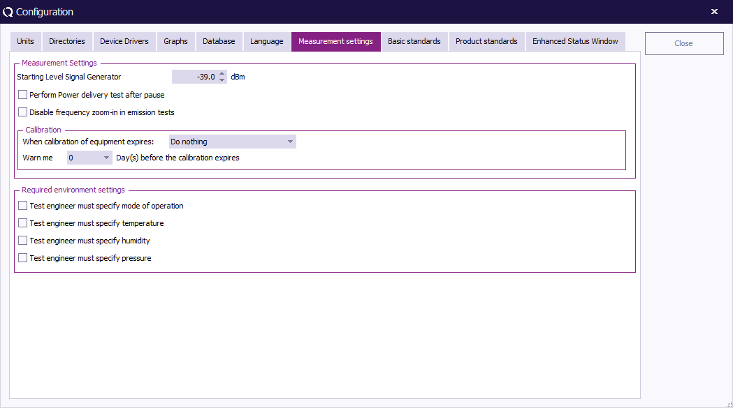
With measurement settings you can change the behavior of the software at certain points. Be very careful what you do with these setting, because they are used through out {{RadiMation}}. | |||
[[Image:Measurement Settings.PNG]] | |||
==== Starting level signal generator ==== | |||
With the 'Starting Level Signal Generator' you can define the level of the signal generator at the start of an immunity test. | |||
==== Perform power delivery test after pause ==== | |||
'Perform Power delivery test after pause' is very helpful if you chose to change the RF path during the pause. | |||
For example: | |||
*Changing the antenna. It will show high refelected power if the antenna is not correctly connected. | |||
*Changing the switch matrix to ensure a safe working area while changing something on the [[EUT]]. It will show you whether or not you are injecting power inside the chamber. | |||
==== Disable frequency zoom-in in emission tests ==== | |||
'Disable frequency zoom-in in emission tests' can be used to decrease the measuring time by not trying to pin point the most accurate frequency. This can be a very useful option for labs that are only interested in the overall envelope of the emission. | |||
{{Warning|Disabling the 'zoom-in in emission tests' in combination with analysers will very likely result in an incorrect measurement.}} | |||
==== Calibration ==== | |||
The 'Calibration' field can be used to specify the behavior of the software with regards to the calibration date of the equipment. This may vary between 'a simple warning message' and 'stopping measurements from being done'. | |||
==== Required environment settings ==== | |||
With the required environment settings you can force the test engineer to fill in specific [[Environmental Data]] settings. The first test done with a new EUT document requires the engineer to fill in the requested information. The second time a button will appear that will allow you to automatically fill in the same information as used in the previous test. | |||
=== 8. Product Standard === | |||
==== Introduction ==== | |||
Product Standards describe the requirements (e.g. dimensional, technical, etc.) and the methods of testing (as well as grading, marking, etc.) of a product. | |||
The objective of these standards is to define and impose 'standards' that will ensure that the product in question will not represent harm or hazard to consumers. | |||
Because the standards with regards to product testing can be relevant to {{RadiMation}} users, {{RadiMation}} offers the possibility to add this documentation to your configuration. | |||
There are many Product Standards for individual products and product types. These, in turn, often refer to multiple Basic Standards. | |||
Where a Product Standard describes all the tests that should be performed on a EUT, a Basic Standard only describes one single test. | |||
For example: | |||
The Product Standard for product X describes four different requirements/tests that the product needs to comply with. | |||
These four tests are described in four Basic Standards, where each basic standard describes the requirements for one test. | |||
Basic Standards can also be added to {{RadiMation}}. | |||
In addition, one single Technical Setup File (TSF) can be generated for each Basic Standard, configured to perform the test as described in the standard. | |||
==== Adding a Product Standard ==== | |||
To add a Product Standard to {{RadiMation}}, go to the ''' 'Configuration' window''' in the ''' 'Configuration' tab'''. | |||
[[Image:Config configuration.png]] | |||
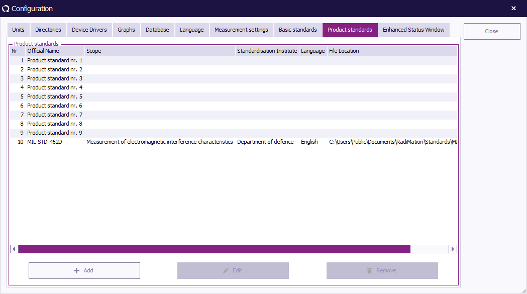
Select the ''' 'Product standards' tab''' and click ''' 'Add' '''. | |||
(To edit a Product Standard, select the standard and click 'Edit'. To remove a Product Standard, select the standard and click 'Remove'.) | |||
[[Image:Configuration ProductStandards.png]] | |||
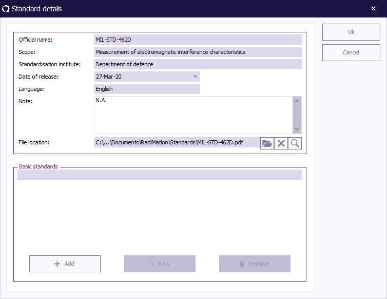
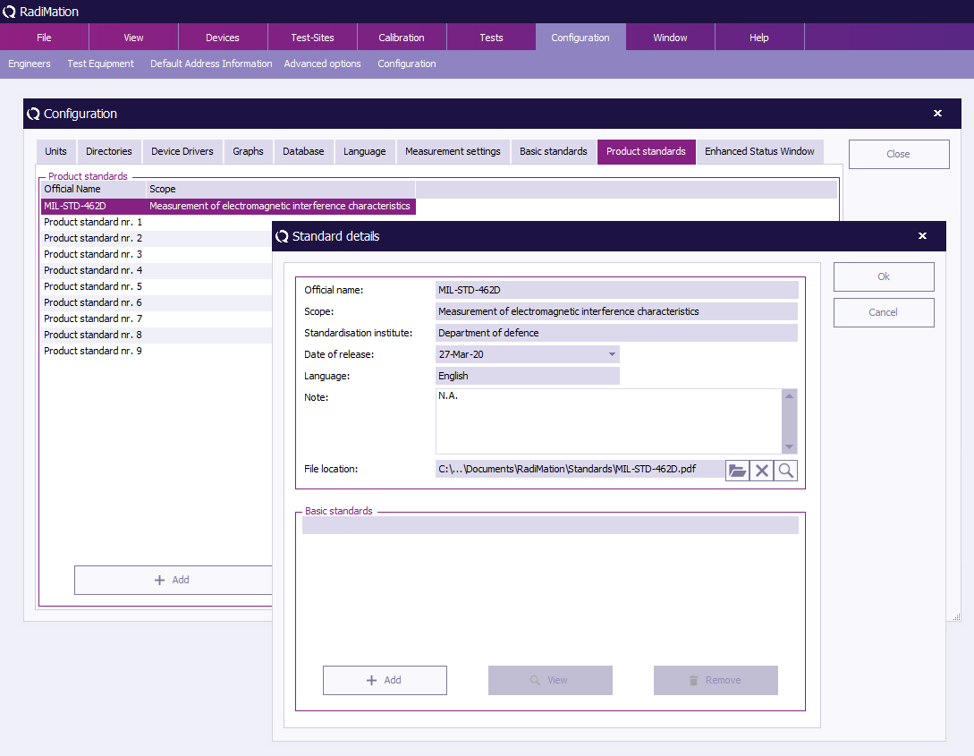
Insert the required information in the ''' 'Standard details' window''' (as visible in the example below). | |||
Please note that the '''Official name''' can only be inserted the first time and has to be unique. | |||
In addition, it is possible to link a file to the standard in the '''File location''' field. For example a PDF, DOC or HTML file that describes the standard. | |||
{{RadiMation}} will open the file (with the default reader for this file type) when the engineer selects the magnifying glass button next to that field. | |||
To confirm your data input, click ''' 'OK' ''', to cancel your input, click ''' 'Cancel' '''. You will be returned to the 'Configuration' window. | |||
[[Image:Product standard details.png]] | |||
==== Add(ing) Basic Standard(s) ==== | |||
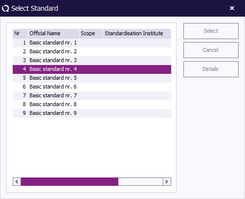
To add a Basic Standard to the product standard, click ''' 'Add' '''. The 'Select Standard' window will appear. | |||
Select one or more Basic Standards (hold the 'Ctrl' key to select multiple standards) and click ''' 'Select' '''. | |||
To cancel your selection, click ''' 'Cancel' '''. You will be returned to the 'Standard details' window. | |||
To see the details of a Basic Standard, double click the standard or click 'Details'. | |||
[[Image:Select basic standard.png]] | |||
{{Note|When a product standard is selected or added in the 'EUT' window, the data of that standard is copied into the EUT Document. At that moment a copy of the data of the standard from the configuration is made. This means that, if the configuration of a standard in the 'Configuration' window of {{RadiMation}} is changed, the data in the EUT file will still have the old data of the standard!!! This is as it should be, because this is the information of the standard that is used at the time that the EUT was tested.}} | |||
=== 9. Basic Standard === | |||
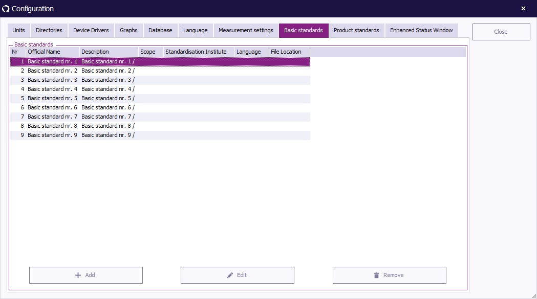
To add a Basic Standard to {{RadiMation}}, go to the ''' 'Configuration' window''' in the ''' 'Configuration' tab'''. | |||
[[Image:Config configuration.png]] | |||
Select the ''' 'Basic standards' tab''' and click ''' 'Add' '''. | |||
(To edit a Basic Standard, select the standard and click 'Edit'. To remove a Basic Standard, select the standard and click 'Remove'. | |||
Please note that removing a Basic Standard from the list will also remove any references of this standard entered in the Product Standards.) | |||
[[Image:Configuration_BasicStandards.png]] | |||
Insert the required information in the ''' 'Standard details' window''' (as visible in the example below). | |||
Please note that the '''Official name''' can only be inserted the first time and has to be unique. | |||
In addition, it is possible to link a file to the standard in the '''File location''' field. For example a PDF, DOC or HTML file that describes the standard. | |||
{{RadiMation}} will open the file (with the default reader for this file type) when the engineer selects the magnifying glass button next to that field. | |||
To confirm your data input, click ''' 'OK' ''', to cancel your input, click ''' 'Cancel' '''. You will be returned to the 'Configuration' window. | |||
[[Image:Basic standard details.png]] | |||
==Correction files== | ==Correction files== | ||
| Line 265: | Line 851: | ||
To create a correction file, select | To create a correction file, select | ||
{{Menu|File|New|Correction file}} | |||
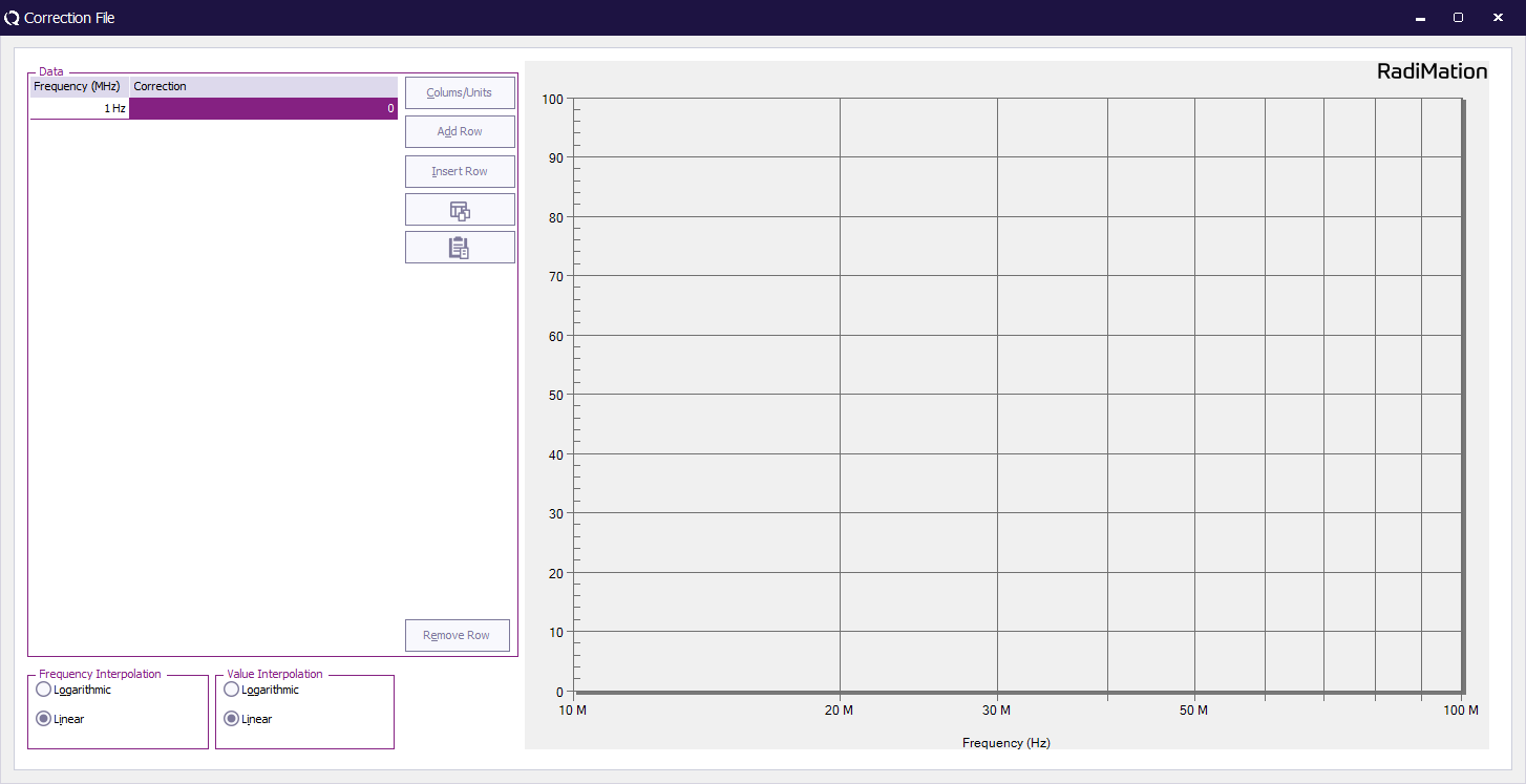
The window below will be displayed. | The window below will be displayed. | ||
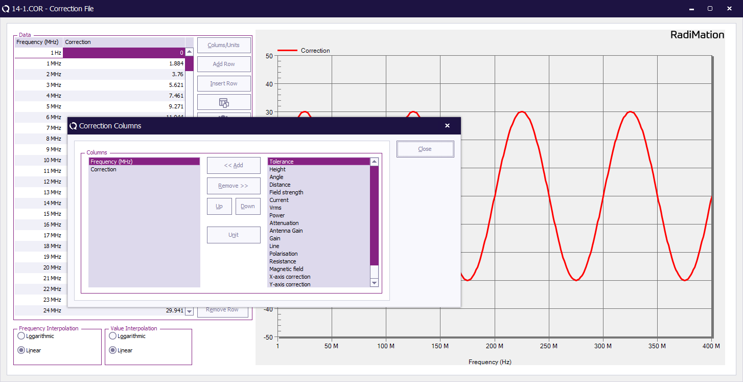
The first step is to define the columns in the table by pushing the Columns/Units button. A selection box appears and columns can be added or removed. Based on the use of the correction file the proper columns should be selected. For example an amplifier correction file will have two columns one frequency column and one power column. In the case of a radiated emission test three columns are required specifying frequency, correction, angle and height. For most columns, a unit can be specified. Values that are specified in this column will be interpreted as being values in the selected unit. | The first step is to define the columns in the table by pushing the Columns/Units button. A selection box appears and columns can be added or removed. Based on the use of the correction file the proper columns should be selected. For example an amplifier correction file will have two columns one frequency column and one power column. In the case of a radiated emission test three columns are required specifying frequency, correction, angle and height. For most columns, a unit can be specified. Values that are specified in this column will be interpreted as being values in the selected unit. | ||
Entering data points | ===Adding and removing columns=== | ||
Correction files are being used to correct for different devices. Look at the end of this chapter for more specific information regarding correction and the correct use in Radimation (What columns to use, what units to use etc). | |||
You can have multiple columns, add/remove columns by using the columns/units button. | |||
[[Image:ColumnsUnits.png]] | |||
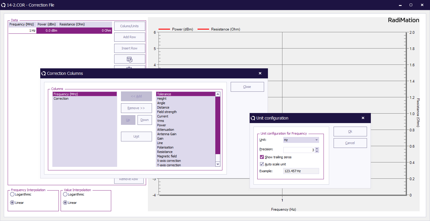
When you have added a column, you will se it on the left-hand side in the list Columns. You can define the unit being used by the column. | |||
This is done by selecting the column and click units. | |||
[[Image:CorrectionUnits.png]] | |||
As an example I have selected the frequency column and here you can define what unit you are using. This is specific for all the different categories. | |||
You will see all units that are normally used to describe the values for the specific category. | |||
====Entering data points==== | |||
Data points can be entered manually and via lists. | |||
To enter data points manually, press the “Add row" button. A new line will appear and you can enter values in the columns. | |||
[[Image:New correction file.png]] | |||
When a data point is incorrect, it can be removed by selecting the data point and pressing the “Remove row” button. To insert a row use "insert row. | |||
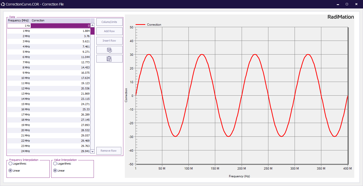
Correction files often contain many points which take a lot of time to enter manually. Equipment manufacturers or calibration facilities often deliver a correction sheet that contains the correction values. a lot of time they deliver a file as well so that you can use this to enter the data. | |||
[[Image:14-CorrectionCurve.png]] | |||
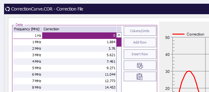
To facilitate this you have two buttons to import and export from the clipboard. This also makes it easy to transfer the data to excel and use calculations if needed. | |||
This can be done from excel files, text files, pdf files etc. In the example above you need two rows: Frequency and Correction. To be able to use the file that has been given by the manufacture to insert the correction data most of the time you have to edit it a bit. In this example this means that you must make sure that the list you are copying to the clipboard looks as follows: | |||
9 29.69 | |||
10 29.68 | |||
etc. | |||
To copy from excel/text file to clipboard or the other way around use the following buttons: | |||
[[Image:FromToClipboard.png]] | |||
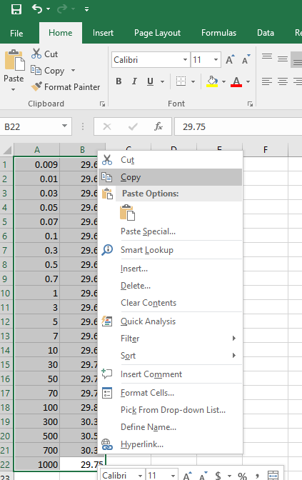
Below you see the list that was used to copy into the correction file to create the correction file that you see in the example above. In this example I have used excel because it is easy to remove columns etc. | |||
[[Image:CorrectionFileExcel.png]] | |||
This can also be done in a text editor just make sure that the information is in nice columns and separated by a space like so: | |||
9 29.69 | |||
10 29.68 | |||
Linear/Logarithmic interpolation | ====Linear/Logarithmic interpolation==== | ||
The user can select either linear or logarithmic frequency interpolation. This choice is dependent on the applicable standard. | The user can select either linear or logarithmic frequency interpolation. This choice is dependent on the applicable standard. | ||
===Saving correction files=== | ===Saving correction files=== | ||
To save the new correction file please select: | To save the new correction file please select: | ||
{{Menu|File|Save correction file}} | |||
{{RadiMation}} will prompt you to enter a filename for the correction file. | |||
===Attaching | ===Attaching correction files=== | ||
Most correction files are used for correcting a measured value of a device driver. The made correction file should | Most correction files are used for correcting a measured value of a device driver. The made correction file should therefore be 'attached' to the correct device driver. | ||
You can attach a correction file to a device driver in the configuration screen. You can access the configuration screen by selecting | You can attach a correction file to a device driver in the configuration screen. You can access the configuration screen by selecting | ||
{{menu|Configuration|configuration}} | |||
in the main menu. The window shown below will appear. | |||
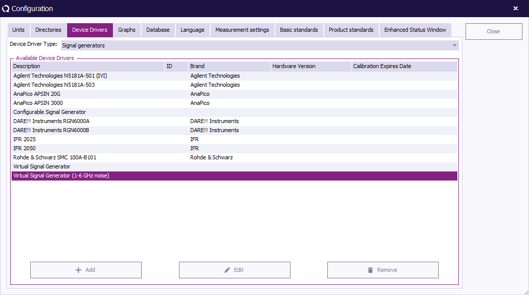
[[Image:Configuration DeviceDrivers.png]] | |||
You can select the type of device you want in the box that is situated top right. The big window will display all currently configured device drivers, like in the picture all configured Signal Generators. | |||
To edit the configuration of a device, select the device in the list and press Edit. | |||
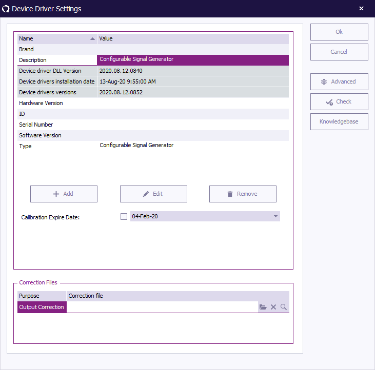
Now you get the configuration window of this specific device driver. | |||
[[Image:Device Driver Settings Window.png]] | |||
In the lower part of this window, the made correction | In the lower part of this window, the made correction file(s) can be selected, for one of the specified uses. The {{RadiMation}} software will use the specified correction files, every time when the device driver is used during a test. In this example it is possible to link an 'Output correction' file to correct the output level of this Signal generator. | ||
Depending on the type of the device driver, different uses of the correction files are available. | Depending on the type of the device driver, different uses of the correction files are available. Remark: it depends on the driver and the used correction 'link', which columns are required and therefore which correction files are acceptable to be used. | ||
==Correction file uses== | ==Correction file uses== | ||
Correction files can be used in many situations. The type and number of columns that should be used in the correction file is depending on the | Correction files can be used in many situations. The type and number of columns that should be used in the correction file is depending on the in which the correction file is used. | ||
=== | ===Absorbing clamp: Clamp loss=== | ||
The | The power loss inside an absorbing clamp can be corrected inside the software. A correction file with the loss should be attached to the device driver of the absorbing clamp. The correction file should contain the columns: | ||
*Frequency | *Frequency | ||
*Correction | *Correction | ||
The values in the correction column should be expressed in | Or | ||
*Frequency | |||
*Attenuation | |||
Or | |||
*Frequency | |||
*Gain | |||
The values in the correction column should be expressed in dB. The values of the correction and attenuation column, are added to the measured emission level. The values in the gain column are subtracted from the measured emission level. In this way the real emission level can be calculated. | |||
===Amplifier Input | ===Amplifier: Maximum Input=== | ||
The input level of an amplifier can be protected to never be above a certain power level. A correction file with the maximum input level should be attached to the device driver of the amplifier. The correction file should contain the columns: | The input level of an amplifier can be protected to never be above a certain power level. A correction file with the maximum input level should be attached to the device driver of the amplifier. The correction file should contain the columns: | ||
*Frequency | *Frequency | ||
| Line 324: | Line 968: | ||
*Frequency | *Frequency | ||
*Power | *Power | ||
The values in the correction column should be expressed in dBm. The value specified in the correction or power column is the maximum power that will | The values in the correction column should be expressed in dBm. The value specified in the correction or power column is the maximum allowed input power of the amplifier. During the regulation of the test-level the regulation is ensuring that the amplifier input power will not become higher than the maximum input power as specified in the correction file. | ||
If no correction file is selected for the 'Maximum Input' of an amplifier device driver, RadiMation will limit the amplifier input power to 0 dBm. 0 dBm is very often the power level that is allowed as maximum amplifier input power without damaging the amplifier. If an amplifier is allowed to have a maximum input power above 0 dBm, a correction file with the allowed value should explicitly be selected for the 'Maximum Input'. | |||
===Amplifier Forward | ===Amplifier: Maximum Forward=== | ||
The forward power level of an amplifier can be protected to never be above a certain power level. A correction file with the maximum forward power level should be attached to the device driver of the amplifier. The correction file should contain the columns: | The forward power level of an amplifier can be protected to never be above a certain power level. A correction file with the maximum forward power level should be attached to the device driver of the amplifier. The correction file should contain the columns: | ||
*Frequency | *Frequency | ||
| Line 333: | Line 979: | ||
*Frequency | *Frequency | ||
*Power | *Power | ||
The values in the correction column should be expressed in dBm. The value specified in the correction or power column is the maximum forward power that will | The values in the correction column should be expressed in dBm. The value specified in the correction or power column is the maximum allowed forward power. During the regulation of the test-level the forward power level is measured and the regulation is ensuring that the forward power will not become higher than the maximum forward power as specified in the correction file. | ||
===Amplifier Reflected | ===Amplifier: Maximum Reflected=== | ||
The reflected power level of an amplifier can be protected to never be above a certain power level. A correction file with the maximum reflected power level should be attached to the device driver of the amplifier. The correction file should contain the columns: | The reflected power level of an amplifier can be protected to never be above a certain power level. A correction file with the maximum reflected power level should be attached to the device driver of the amplifier. The correction file should contain the columns: | ||
*Frequency | *Frequency | ||
| Line 342: | Line 988: | ||
*Frequency | *Frequency | ||
*Power | *Power | ||
The values in the correction column should be expressed in dBm. The value specified in the correction or power column is the maximum reflected power. During the regulation of the test-level is | The values in the correction column should be expressed in dBm. The value specified in the correction or power column is the maximum allowed reflected power. During the regulation of the test-level the reflected power level is measured and the regulation is ensuring that the reflected power will not become higher than the maximum reflected power as specified in the correction file. | ||
=== | ===Antenna: Ant Gain vs Angle=== | ||
The | This correction is only available when the Antenna Diagram module is activated. The antenna gain is depend on the measuring angle during antenna diagram measurements. A correction file can be used to specify the AntennaGain depending on the receiving angle. This correction file should be attached to the device driver of the antenna. The correction file should contain the columns: | ||
*Angle | |||
*Attenuation | |||
The value of the attenuation column is added to the measured radiated power. | |||
===Antenna: Antenna Efficiency === | |||
The Antenna Efficiency is used to indicate the Efficiency of the antenna. | |||
The Antenna Efficiency is expressed as a unit less number and the value should be between -1 and 1. | |||
The correction file should contain the columns: | |||
*Frequency | *Frequency | ||
*Correction | *Correction | ||
Where the values in the correction column are used as a correction which is added on top of the the Antenna Efficiency that is specified in the antenna device driver itself. | |||
===Antenna: Antenna Factor=== | |||
For converting the reading dBμV into dBμV/m the antenna factor is needed. This is expressed as dB/m. | |||
The correction file should contain the columns: | |||
*Frequency | *Frequency | ||
* | *Correction | ||
Where the correction column is the antenna factor. The values are added to the calculation to account for the non-linearity in the antenna. | |||
===Antenna: Antenna Gain=== | |||
The Antenna Gain correction is used to correct the calculated logarithmic gain for horn antennas based on their horn dimensions. | |||
This value is used by the calculations applicable to the calculated electrical field test levels. | |||
The Antenna Gain is expressed in dB(i) | |||
The correction file should contain the columns: | |||
*Frequency | *Frequency | ||
* | *Antenna gain | ||
===Antenna: GpsHt - AntHeight=== | |||
This correction is only available when the Antenna Diagram module is activated. The height distance between the GPS receiver and the Antenna can be corrected by a correction file. A correction file with the height distance should be attached to the device driver of the antenna. The correction file should contain the column: | |||
*Height | |||
Only one row should be present in the correction file. If multiple rows are available, only the height value of the first row will be used. The value of the height column, is subtracted from the height received by the GPS receiver. The result is the exact height of the receiving antenna for the antenna diagram measurements. | |||
=== | ===Antenna: Magnetic Flux Density (pT/A) correction=== | ||
During immunity measurements when a magnetic field has to be generated, this correction file is used to determine the current that should be generated during the magnetic field generation loop antenna. A correction file with the correction factor should be attached to the device driver of the antenna. The correction file should contain the columns: | |||
*Frequency | *Frequency | ||
*Correction | *Correction | ||
The value specified in the correction column should be expressed in pT/A. The values in the correction column are multiplied with the generated current to calculate the generated magnetic field in picoTesla (pT). | |||
This correction is primarily used during the [[MIL-STD-461]] RS101 magnetic field tests. In the MIL-STD 461, this correction value is specified as 9.5x10^7 pT/A. | |||
===Antenna: Magnetic Field Factor (dBpT/uV) correction=== | |||
During emission measurements when the measured emission values have to be shown in magnetic field (Tesla) units, the correction factor should be configured in the software. A correction file with the correction factor should be attached to the device driver of the antenna. The correction file should contain the columns: | |||
*Frequency | *Frequency | ||
* | *Correction | ||
The value specified in the correction column should be expressed in dBpT/uV. The values in the correction column are added to the measured emission levels from the measurement receiver to calculate the correct to be displayed emission values in a Tesla unit. | |||
This same correction is also used during the [[MIL-STD-461]] RS101 Magnetic Field calibration for the 'calibration antenna'. | |||
The value specified in the | |||
===Antenna: Reflection coefficient=== | |||
The Reflection coefficient is used to correct the calculated required netto power in Watts for horn antennas to a calculated required forward power level in Watts. | |||
The Reflection coefficient is expressed as a unit less number. | |||
The correction file should contain the columns: | |||
*Frequency | *Frequency | ||
*Correction | *Correction | ||
Where the correction column is the Reflection coefficient. | |||
===Cable: Cable loss=== | |||
===Cable loss | |||
The power loss inside a cable can be corrected inside the software. A correction file with the cable loss should be attached to the device driver of the cable. The correction file should contain the columns: | The power loss inside a cable can be corrected inside the software. A correction file with the cable loss should be attached to the device driver of the cable. The correction file should contain the columns: | ||
*Frequency | *Frequency | ||
| Line 389: | Line 1,066: | ||
*Frequency | *Frequency | ||
*Gain | *Gain | ||
The values in the correction column should be expressed in dB. Cable device drivers can be used in different parts of a test-site setup. But they all have in common that an 'interesting' power-level is attenuated by the cable before it is measured by a measuring device (most of the time a powermeter, | The values in the correction column should be expressed in dB. Cable device drivers can be used in different parts of a test-site setup. But they all have in common that an 'interesting' power-level is attenuated by the cable before it is measured by a measuring device (most of the time a powermeter, receiver or an analyser). The values of the correction and attenuation column are therefore added to the measured powerlevel. The values in the gain column are inverted before they are added to the measured powerlevel. | ||
=== | ===Calibration Jig: Transfer correction=== | ||
The | The transfer factor of a calibration jig can be corrected inside the software. A correction file with the correction should be attached to the device driver of the calibration jig. The correction file should contain the columns: | ||
*Frequency | *Frequency | ||
*Correction | *Correction | ||
The value specified in the correction column should be expressed in dB and the value is added to the typical transfer factor of a calibration jig. For example: A calibration jig is used with a typical transfer factor of 9.6 dB (correction for 150 {{Ohm}} to 50 {{Ohm}}). A correction file with a frequency and correction column is connected to the device driver. The value specified in the correction column for 1.23 MHz. is 0.3 dB. Then the software will use a total transfer factor for the calibration jig of 9.9 dB. | |||
If the jig is not "Configurable" there is a default correction factor of 9.5 dB (theoretical value). We will explain how the presence of a correction factor is it taken into account by RadiMation and how this value is used by an example. For instance we have the following situation: At 150 kHz the real total correction factor of the jig is 10 dB. When this value is saved in the correction file, what will be the behavior of RadiMation? Will it now take the 10 dB as the total transfer correction? The answer is that the correction value will be added, but RadiMation will use this specified 10 dB correction on top of the internal correction value. In this case it is not correct and a correction of app. 0,5 should have been used. | |||
There are two categories of Injection devices: | |||
* 50 Ohm. (E.g. Luthi CR 100 A, Tegam 95241, FCC BCICF) | |||
* 150 Ohm. (E.g. Luthi EM 101, MEB KAL-M2, MEB KAL-KEMZ, FCC F-203I-CF-23mm) | |||
Depending on the used injection device, a matching calibration jig is necessary to correctly calibrate the injection device. Based on the impedance of the injection device, the calibration jig should be corrected with a value. In RadiMation we use the principle that we already programmed the correct correction value in the device driver of the calibration jig. This simplifies the implementation of our software, as you only have to select the correct device driver, and RadiMation automatically knows the correct correction value for the calibration jig. | |||
This implies that: | |||
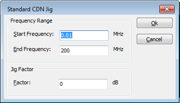
* The device drivers for the calibration jigs for the 50 Ohm injection devices already have an internal correction factor of 0 dB. | |||
* The device drivers for the calibration jigs for the 150 Ohm injection devices already have an internal correction factor of 9.5 dB (9.5424 dB to be more exact). | |||
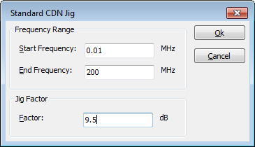
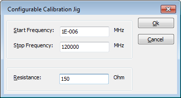
We are aware that it is not very clearly visible which correction factor is used inside a device driver of the calibration jig. That is why the newer device drivers, report the frequency range and the correction factor that is programmed inside the RadiMation device driver of a calibration jig. When you want to retrieve this information (shown in a 1 digit precision) just press the 'Advanced' button on the device driver configuration window. | |||
In this example we are using a jig for a CDN where the jig has 100 Ohm resistors in the connection. In this case a 150 Ohm system (as the 100 Ohm resistors are in series with the coax which already has a 50 Ohm resistance) is used. | |||
The calibration jig value (as a factor or as a resistance) is only used for a conversion of the impedance of the CDN to the 50 Ohm typical impedance of the coax cables and powermeters. | |||
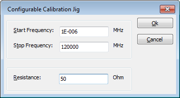
In some RadiMation device drivers a resistance should be specified, and in other device drivers a calibration jig factor should be specified. If a resistance should be specified in a device driver, the calibration jig factor is calculated using the formula: | |||
calibration jig factor = 20 * log10(<resistance [Ohm]> / 50) | |||
For a 150 Ohm system the correct jig transfer factor is 9.5 dB. Depending on the selected calibration jig device driver a calibration jig factor of 9.5 dB should be selected: | |||
[[Image:Calibration_jig_factor_9.5_dB_for_150_Ohm_system.png]] | |||
or a resistance of 150 Ohm should be specified for the 150 Ohm system: | |||
[[Image:Calibration_jig_factor_150_Ohm_for_150_Ohm_system.png]] | |||
For a 50 Ohm system, (where no 100 Ohm resistors are included in the calibration jig) the calibration jig factor should be 0 dB: | |||
[[Image:Calibration_jig_factor_0_dB_for_50_Ohm_system.png]] | |||
or a resistance of 50 Ohm should be specified: | |||
[[Image:Calibration_jig_factor_50_Ohm_for_50_Ohm_system.png]] | |||
== Using a transfer correction file provided by the supplier == | |||
Sometimes a file with values for the transfer correction is delivered by the manufacturer. It is unusual and does not happen that often. If you would like to use the transfer file provided by the manufacturer you have to set the correction factor described above to zero dB. The correction file is then attached directly to the jig. However you should then use a congifurable driver for the jig where you manually set the transfer factor to 0dB. If you use the original driver then the correction factor is added with the programmed factor for that driver. | |||
Normally it is not needed to add this transfer file and using the correct driver for the jig should have the correct factor already added nominally. It is also unusual for manufacturers to add the transfer factor but sometimes this is delivered. | |||
===Coupler: Forward Correction=== | |||
The forward power attenuation of a coupler can be corrected by a correction file. A correction file with the correction should be attached to the device driver of the coupler. The correction file should contain the columns: | |||
* Frequency | |||
* Correction. The values in the 'Correction' column should be expressed in dB, and these values are added to the typical attenuation of the coupler. | |||
Or | Or | ||
*Frequency | * Frequency | ||
*Attenuation | * Attenuation. The values in the 'Attenuation' column are added to the typical attenuation of the coupler. | ||
Or | Or | ||
*Frequency | * Frequency | ||
*Gain | * Gain. The values specified in the 'Gain' column are subtracted from the typical attenuation of the coupler. | ||
The values in the | |||
For example: A coupler is used with a typical forward attenuation of 60 dB. A correction file with a frequency and attenuation column is connected to the device driver. The value specified in the attenuation column for 100 MHz is 1.3 dB. Then the software will use a value of 61.3 dB for the total attenuation of the coupler. | |||
=== | ===Coupler: Reflected Correction=== | ||
The | The reflected power attenuation of a coupler can be corrected by a correction file. A correction file with the correction should be attached to the device driver of the coupler. The correction file should contain the columns: | ||
*Frequency | *Frequency | ||
*Correction | *Correction | ||
| Line 413: | Line 1,144: | ||
*Frequency | *Frequency | ||
*Gain | *Gain | ||
The value specified in the gain column is substracted from the typical attenuation of the coupler. The values in the correction or attenuation column is added to the typical attenuation of the coupler. For example: A coupler is used with a typical reflected attenuation of 40 dB. A correction file with a frequency and attenuation column is connected to the device driver. The value specified in the attenuation column for 130 kHz. is 0.13 dB. Then the software will use a value of 40.13 dB for the total attenuation of the coupler. | |||
===Current sensor: impedance=== | |||
The impedance of a current sensor is very important to calculate the correct measured current. The impedance is current sensor and frequency dependant. Before a current sensor can be used, an impedance correction file should be attached to the device driver of the current sensor. The value specified in the correction file is used to correctly calculate the current flowing through the current sensor. The correction file should contain the columns: | |||
* Frequency | |||
* Correction. The values in the 'Correction' column should be expressed in Ohm ({{Ohm}}). | |||
Or | Or | ||
*Frequency | * Frequency | ||
* | * Resistance. The values in the 'Resistance' column will use the unit that is configured for the 'Resistance' column. | ||
The values in the correction column should be expressed in | |||
===Field sensor: Field offset=== | |||
The measured value of a field sensor, can be corrected by the software. The measured value can be corrected with an offset, or it can be corrected by a multiply factor. Both corrections can also be used together but the multiply correction will be performed first, and after that the offset correction will be added. The correction files with the correction should be attached to the device driver of the field sensor. The correction file for the field offset should contain the columns: | |||
* Frequency | |||
* Correction. The values in the column used for the offset correction should be expressed in V/m. This correction is then applied on the isotropic value. | |||
or | |||
* Frequency | |||
* X-axis correction. The values in the column used for the offset correction should be expressed in V/m. This correction is applied on the x-axis reading only. | |||
* Y-axis correction. The values in the column used for the offset correction should be expressed in V/m. This correction is applied on the y-axis reading only. | |||
* Z-axis correction. The values in the column used for the offset correction should be expressed in V/m. This correction is applied on the z-axis reading only. | |||
When the correction is specified for the individual axis, those axis are first corrected, after which the isotropic value is calculated based on the individually corrected axes. | |||
To summarize this in an example, let’s assume that the uncorrected field probe measurement at 90 MHz is 10.2 V/m. When a Field offset isotropic correction for that same frequency of 2.0 V/m is specified, RadiMation will use a corrected field strength of 12.2 V/m (10.2 V/m + 2.0 V/m). | |||
=== | ===Field sensor: Field Multiply=== | ||
The | The measured value of a field sensor, can be corrected by the software. The measured value can be corrected with an offset, or it can be corrected by a multiply factor. Both corrections can also be used together but the multiply correction will be performed first, and after that the offset correction will be added. The correction files with the correction should be attached to the device driver of the field sensor. The correction file for the multiply should contain the columns: | ||
*Frequency | * Frequency | ||
*Correction | * Correction. The values in the column used for the multiply correction should be expressed as x (multiplier). This correction is then applied on the isotropic value. | ||
The | or | ||
* Frequency | |||
* X-axis correction. The values in the column used for the multiply correction should be expressed as x (multiplier). This correction is applied on the x-axis reading only. | |||
* Y-axis correction. The values in the column used for the multiply correction should be expressed as x (multiplier). This correction is applied on the y-axis reading only. | |||
* Z-axis correction. The values in the column used for the multiply correction should be expressed as x (multiplier). This correction is applied on the z-axis reading only. | |||
When the correction is specified for the individual axis, those axis are first corrected, after which the isotropic value is calculated based on the individually corrected axes. | |||
To summarize this in an example, let’s assume that the uncorrected field probe measurement at 90 MHz is 10.2 V/m. When a Field multiply isotropic correction for that same frequency of 1.1x is specified, RadiMation will use a corrected field strength of 11.22 V/m (10.2 V/m * 1.1). | |||
===LISN Amplitude correction=== | ===LISN: Amplitude correction=== | ||
The power loss inside an LISN can be corrected inside the software. A correction file with the correction should be attached to the device driver of the LISN. The correction file should contain the columns: | The power loss inside an LISN can be corrected inside the software. A correction file with the correction should be attached to the device driver of the LISN. The correction file should contain the columns: | ||
*Frequency | *Frequency | ||
| Line 453: | Line 1,188: | ||
The values in the correction column should be expressed in dB. The values of the correction column are added to the measured emission level. In this way the real emission level can be calculated. | The values in the correction column should be expressed in dB. The values of the correction column are added to the measured emission level. In this way the real emission level can be calculated. | ||
=== | ===Powermeter: Power correction=== | ||
The gain of an used preamplifier can be corrected inside the software. A correction file with the frequency | The measured power level of a power meter can be corrected with a certain value. A correction file with the correction should be attached to the device driver of the powermeter. The correction file should contain the columns: | ||
*Frequency | * Frequency | ||
*Correction | * Correction | ||
The values in the | or | ||
* Frequency | |||
* Attenuation | |||
or | |||
* Frequency | |||
* Gain | |||
The values in the correction column should be expressed in dB. The value specified in the attenuation column is subtracted from the measured power level. The values in the correction or gain column is added to the measured power level. For example: A power level of -14.58 dBm is measured with a power-meter. A correction file with a frequency and attenuation column is connected to the device driver. The value specified in the attenuation column for 81.7 MHz. is 0.27 dB. Then the software will use a value of -14.85 dBm as the value that was measured with the power-meter. | |||
===Pre amplifier: Amplifier Gain=== | |||
The gain of an used preamplifier can be corrected inside the software. A correction file with the frequency dependent gain of the preamplifier should be attached to the device driver of the preamplifier. The values in the correction column should be expressed in dB. | |||
The actually used calculation is depending on the configuration of the correction file that is selected for the preamplifier. The correction file can contain the columns: | |||
* Frequency | |||
* Correction: The values in the Correction column are interpreted as 'gain' values. A positive value is interpreted as a positive amplification of the preamplifier. These 'gain' values will be subtracted from the values that are measured with the receiver/analyser. | |||
or | |||
* Frequency | |||
* Gain: The values in the Gain column are interpreted as 'gain' values. A positive value is interpreted as a positive amplification of the preamplifier. These 'gain' values will be subtracted from the values that are measured with the receiver/analyser. | |||
or | |||
* Frequency | |||
* Attenuation: The values in the Attenuation column are interpreted as 'attenuation' values. A positive value is interpreted as a loss caused by the preamplifier. A negative value is interpreted as a positive amplification of the signal, caused by the preamplifier. These 'attenuation' values will be added to the values that are measured with the receiver/analyser. | |||
===Receiver | ===Receiver: Amplitude correction=== | ||
The power loss inside a receiver or a spectrum analyser can be corrected inside the software. A correction file with the loss should be attached to the device driver of receiver of spectrum analyser. The correction file should contain the columns: | The power loss inside a receiver or a spectrum analyser can be corrected inside the software. A correction file with the loss should be attached to the device driver of receiver of spectrum analyser. The correction file should contain the columns: | ||
*Frequency | *Frequency | ||
| Line 465: | Line 1,220: | ||
The values in the correction column should be expressed in dB. The values of the correction column are added to the measured emission level. In this way the real emission level can be calculated. | The values in the correction column should be expressed in dB. The values of the correction column are added to the measured emission level. In this way the real emission level can be calculated. | ||
===Correction | ===Resistor: Resistance Correction=== | ||
The typical value of a used resistor can be corrected by a correction file. A correction file with the correction should be attached to the device driver of the resistor. The correction file should contain the columns: | |||
*Frequency | *Frequency | ||
*Correction | *Correction | ||
The value specified in the correction column should be expressed in Ohm. The values in the correction column is used in the | The value specified in the correction column should be expressed in Ohm ({{Ohm}}). The values in the correction column is added to the typical resistance of the resistor. For example: A resistor of 0.5 {{Ohm}} is used. A correction file with a frequency and correction column is connected to the device driver. The value specified in the correction column for 594 kHz. is 0.04 {{Ohm}}. Then the software will use a value of 0.54 {{Ohm}} for the exact value of its calculations with the resistor. | ||
===Signal Generator: Output Correction=== | |||
The output level of a signal generator can be corrected. A correction file with the correction should be attached to the device driver of the signal generator. The correction file should contain the columns: | |||
*Frequency | *Frequency | ||
*Correction | *Correction | ||
The | The values in the correction column should be expressed in dBm. The value specified in the correction column is added to the desired carrier level and then send to the signal generator. For example: a signal generator that outputs 0.2 dB more than is specified on its display, can be corrected with a value of: -0.2 | ||
[[Category:Manual]] | |||
Latest revision as of 12:57, 29 August 2024
Configuration[edit]
The global configuration of RadiMation® is available in the menu
-
 Configuration
-
The configured global RadiMation® configuration will be used as the configuration for future use. This configuration is independent of the actual Windows User Account that is logged on to the Microsoft Windows PC. The configured global RadiMation® configuration is shared and accessible for all Windows User Accounts that have access to the PC.
The following paragraphs will explain all the possible configurations.
| Warning: | To prevent unauthorised individuals from changing the global RadiMation® configurations, a password protection can be used for specific engineers. The password is activated by default for the "Administrator" engineer with the password "Radimation". This password protection can be switched off, changed and configured in the menu
|
Engineers[edit]
On a new installation, only a single 'Administrator' engineer is created by default. An unlimited number of engineers can be added, each with an unique name. For each engineer a login password and different permissions can be assigned which give them the right to modify specific parts of the RadiMation® configuration. There is no relation between the engineer in RadiMation® and the Windows Logon account. Also the password that can be configured for the engineer in RadiMation® is not linked and also not synchronized with the Windows User account password.
During the startup of RadiMation® the actual engineer that is going to start tests can be selected in the Login dialog. If a password is configured for that engineer, it should also be specified at that moment.
Automatic login of the engineer can be disabled or enabled. If it is enabled, it can only be selected for one engineer, and that engineer will be automatically logged in the next time that RadiMation® starts. If the Automatically login with this engineer checkbox is selected for an engineer, the automatic login of all the other engineers will not be performed anymore. For changing setting of the the automatically logged in engineer, it is still necessary to close the login dialog by specifying the corresponding Password and using the Ok button.
Switching between the active engineers while RadiMation® is running can be done through the menu:
-
 File
File
-
 Change Engineer
-
-
To add, delete or edit the names and permissions of the engineers, go to the Engineers window, which can be accessed in the menu:
-
 Configuration
-
 Engineers
-
-
The Engineers window will open and show the current configured list of engineers.
Test engineer settings[edit]
To leave the 'Engineers' window, click OK.
Adding an engineer[edit]
To add a new test engineer to the configuration, click Add.
Enter the name and set the rights of the new engineer, then click OK. You will be returned to the 'Engineers' window.
The new engineer will not have a protection password (yet), this can be enabled by clicking Change Password. Please read the paragraph 'Password protection' (located further down) for more information.
Deleting an engineer[edit]
To delete a test engineer from the configuration, select the engineer and click Delete.
To confirm that you want to delete the engineer from the configuration list, click Yes.
If you do not want to delete this engineer from the list, click No or Cancel. You will be returned to the 'Engineers' window.
Editing engineer settings[edit]
To edit the name, rights and/or password of an engineer in the configuration, select the engineer and click Edit.
Make the desired changes in the 'Test Engineer' window and click OK.
If you want to undo or cancel your changes, click Cancel. You will be returned to the 'Engineers' window.
Password protection[edit]
RadiMation® allows you to protect a number of configurations with a password. This password can be enabled, disabled or changed in the 'Test Engineer' window.
- The password is standard turned on for the default used test engineer 'Administrator'.
- The default password is Radimation.
The current password setting for the selected engineer is displayed at the bottom of this window. This will indicate whether a password has been 'set' or 'not set'.
Rights[edit]
The password protection can be enabled or disabled for the following items.
| Prevents unauthorized changes to test equipment configuration. |
| Prevents unauthorized changes to test engineers configuration. |
| Prevents unauthorized changes to Test Setup Files (TSF) files. |
| Prevents unauthorized changes to Limit Line Files (LLF) files. |
| Prevents unauthorized changes to correction files. |
| Prevents unauthorized changes to the general configuration. |
Change password[edit]
To enable, disable or change the password, click Change Password.
To change the password, enter the old password and the new password (twice), then click OK. You will be returned to the 'Test Engineer' window.
To disable the password, enter the old password and leave the two new password fields empty, then click OK. You will be returned to the 'Test Engineer' window, and the password indication will change to: “Warning: Password is not set for this engineer.”
To enable the password, enter the new password (twice), then click OK. You will be returned to the 'Test Engineer' window, and the password indication will change to: “Password is set for this engineer.”
To leave the 'Engineers' window, click OK.
Test Equipment[edit]
The test equipment configuration contains a list of all the test equipment used during a test. The software uses this list to determine which device drivers should be used to control the test equipment. RadiMation® allows you to configure specific test equipment lists for each type of test as well as different test equipment lists for the same type of tests. (This can be useful if you have, for example, more than one signal generator to perform conducted immunity tests with).
In the 'Test Equipment' window a set of test equipment will be selected. When a calibration file is generated, RadiMation® will record this test equipment configuration together with the calibration data. When a substitution test is started, the test equipment selected for the substitution test will be compared with the test equipment used (as recorded) during the calibration test. If the equipment does not match, an error message will be displayed.
The error message window will ask you to abort the test or to ignore the error message and continue the test with different test equipment. To achieve maximum accuracy, the same test equipment should be used (whenever possible) during both the calibration and the substitution tests.
To add, modify or delete test equipment lists, go to the 'Test Equipment' window in the 'Configuration' tab.
The 'Test Equipment' window will open and show the current configured list of test equipment. To leave the 'Test Equipment' window, click 'Close' .
Adding test equipment[edit]
To add a (set of) test equipment to the configuration, click the 'Add' button in the top of the window. The 'New Test Equipment' window will appear.
Enter a name for the new test equipment in the 'New Test Equipment' window (e.g. Example Test Equipment).
Click 'OK' to confirm the name of the new test equipment, or click 'Cancel' to cancel the new name. You will be returned to the 'Test Equipment' window.
Deleting test equipment[edit]
To delete a (set of) test equipment from the configuration, select the Test Equipment from the pull down menu and click the 'Delete' button in the top of the window. A confirmation window will appear.
Click 'Yes' to remove the device from the list, click 'Cancel' to cancel. You will be returned to the 'Test Equipment' window.
Editing test equipment[edit]
To configure the equipment of a test, select the desired Test Equipment from the pull down menu (e.g. Example Test Equipment).
Specify the equipment for the test by adding, editing and/or removing devices under the designated tabs. (This is described further below.)
Devices 1 & 2[edit]
Under the tabs 'Devices 1' and 'Devices 2' the devices of the (selected) test equipment set can be added, edited and/or removed.
Adding devices[edit]
To add a device, click 'Add' (at the bottom left of the window), a menu will open below the button to show the available devices for each Device Type.
Select and click on the desired device. The device will then appear in the equipment overview.
Another way to add a device is to click the desired Device Type in the 'Test Equipment' overview.
A menu will open (at your mouse point) with the available devices for that Device Type.
Select and click on the desired device. The device will then appear in the equipment overview.
Editing devices[edit]
To edit a device, select the device and click 'Edit' . The Device Driver Settings window will appear.
Edit the settings as desired. To confirm your changes, click 'OK' , to cancel your changes, click 'Cancel' . You will be returned to the 'Test Equipment' window.
Removing devices[edit]
To remove a device, select the device and click 'Remove' . A confirmation window will appear.
Click 'Yes' to remove the device from the list, click 'Cancel' to cancel. You will be returned to the 'Test Equipment' window.
Saving test equipment[edit]
To save the changes made in the test equipment list, click 'Save' (you will remain in the 'Test Equipment' window).
Save As[edit]
To save the test equipment list under a new name, click 'Save As' .
Enter a new name for the test equipment in the 'New Test Equipment' window (e.g. Example Test Equipment 2).
Click 'OK' to confirm the name of the new test equipment, or click 'Cancel' to cancel the new name. You will be returned to the 'Test Equipment' window.
To close the 'Test Equipment' window, click 'Close' .
If you have not saved the changes to the test equipment list, a dedicated window will appear asking you to save these changes.
To save the changes, click 'Yes' , to not save the changes, click 'No' . The 'Test Equipment' window will close.
Before Actions & After Actions[edit]
The before and after actions of a testsite are designed to be triggered when the testsite is activated (before actions) or deactivated (after actions). These before and after actions can be seen as like switching relays to desired positions when a testsite is activated, and switching the relays to a default position again when the testsite is deactivated.
When a testsite is used in two consecutive bands, the after and before actions are not executed, because there is no change in the activated testsite. When a test with 3 bands is configured, and the first and third band are using the same testsite, while another testsite is selected for the second band, then the after and before actions will be executed when the test is switching from band 1 to band 2, and again when the test is switching from band 2 to band 3.
Before Action[edit]
Under the tab 'Before Action' any and all actions that the end-user wants to have carried out before the equipment of the selected 'test equipment' is initialized can be specified.
'Before actions' can be used to:
- Turn on a manual controlled amplifier.
- Manually change antenna height or polarization.
- Connect cables or create a specific measurement setup.
(It is also possible to specify actions that should be carried out after the equipment of the selected Test Equipment is disabled. This functionality is called 'After Action'.)
The easiest way to explain this function is with an example:
Example[edit]
RadiMation® needs to be configured for people who do not perform EMC measurements every day. To make sure the engineers do not forget to use the right equipment and procedure, the manager has decided to incorporate a reminder in the test setup.
This is done by adding a message in the 'Before Action' configuration:
1. Open the 'Test Equipment' window, select the desired test equipment set and open the 'Before Action' tab.
2. Press the 'Add' button at the bottom left of the 'Before Action' tab to open the 'Add Action' window.
3. Select the 'Messagebox' option and click 'OK' (or double click on the 'Messagebox' option). A dedicated window will appear.
4. Configuring the desired text in the 'Messagebox Configuration' window and click 'OK' . You will be returned to the 'Test Equipment' window.
The message has now been added to the configuration. As a result, RadiMation® will prompt the following message before the test equipment is initialized:
After Action[edit]
Under the tab 'After Action' any and all actions that the end-user wants to have carried out after the equipment of the selected 'test equipment' is disabled can be specified.
'After actions' can be used to:
- Manually turn off the amplifier.
- Play a Wav file (as an auditory signal) to alert the user that the measurement is done.
(It is also possible to specify actions that should be carried out before the equipment of the selected Test Equipment is initialized. This functionality is called 'Before Action'.)
Default address information[edit]
When a new EUT file is created, the name and address information of the client, manufacturer and test site can be entered.
In many situations one or more of those address information will be the same for different EUT files (for example, when a test site use RadiMation®, the test site address information will always be the same).
To prevent users from having to enter repetitive data input, RadiMation® provides the possibility to set default address information for:
- the client that has ordered that tests should be performed on the EUT
- the manufacturer that has produced the EUT
- the test site that is performing the tests on the EUT
Address information entered on the Default Address Information window, will be automatically included on the EUT window and therefore only needs to be entered once.
To add, modify or delete the default address information, use the menu:
-
 Configuration
-
 Default Address Information
-
-
In the Default Address Information window, the default address information can be configured. Specifying this information is not required, however it has the benefit that address information that is always the same doesn't need to be entered over and over again in every new EUT file.
| The default company name for the client. |
| The default contact person for the client. |
| The default address for the client. |
| The default zip code for the client. |
| The default city for the client. |
| The default state for the client. |
| The default country for the client. |
| The default telephone number for the client. |
| The default fax numberfor the client. |
| The default e-mail address for the client. |
| The default company name for the manufacturer. |
| The default contact person for the manufacturer. |
| The default address for the manufacturer. |
| The default zip code for the manufacturer. |
| The default city for the manufacturer. |
| The default state for the manufacturer. |
| The default country for the manufacturer. |
| The default telephone number for the manufacturer. |
| The default fax number for the manufacturer. |
| The default e-mail address for the manufacturer. |
| The default company name for the test site. |
| The default contact person for the test site. |
| The default address for the test site. |
| The default zip code for the test site. |
| The default city for the test site. |
| The default state for the test site. |
| The default country for the test site. |
| The default telephone number for the test site. |
| The default fax number for the test site. |
| The default e-mail address for the test site. |
| Stores the modified information and closes the window. |
| Discards the modified information and closes the window. |
The default address information is stored in the Device Driver Configuration Files directory, which can be configured in the global RadiMation® configuration.
Advanced options[edit]
There are a several advanced options in RadiMation®, that allow to tune or optimize some specific settings. Making changes to one or more of those settings, can have a major influence in the correct functioning of the software. Changes to one or more of these advanced options are only needed to circumvent a specific situation. Before changes can be made, a specific password should be specified. The required password is not related to any of the passwords of existing engineers. If it is necessary to make a change to one or more of the advanced options, the password will be provided to the end-user by the reseller or Raditeq If the password is specified correctly, a configuration window is shown that includes a table to review and edit the list of advanced options.
Configuration[edit]
RadiMation® allows the user to define an extensive default configuration. This includes the settings for the:
- Units
- Directories
- Device Drivers
- Graphs
- Database
- Language
- Measurement settings
- Product standards
- Basic standards
- Enhanced Status Window
Each of these settings are available on a specific tab in the global configuration which can be accessed through the menu:
-
 Configuration
-
 Configuration
-
-
1. Units configuration[edit]
The default settings for the different units can be set in the 'Units' tab. These units are used throughout the software package and can be changed at any time during measurements and viewing.
It is possible to define different units for different tests. The following can be selected:
- Radiated Immunity
- Conducted Immunity
- Radiated Emission
- Conducted Emission
- Pulsed Immunity
- Antenna Diagram
- RadiCal
Changing unit settings[edit]
To change the settings of a unit, choose the desired test (e.g. Radiated Immunity) from the drop down menu in the 'Units' tab.
Select the measurement (e.g. Power) and click 'Change' .
The 'Unit configuration' window will appear, allowing you to change the parameters of the unit.
To confirm your changes, click 'OK' , to cancel your changes, click 'Cancel' . You will be returned to the 'Configuration' window.
Click 'Close' to leave the 'Configuration' window.
2. Directories configuration[edit]
The RadiMation® software can use different directories to store different files.
The location of the Device Driver Configuration Files can be specified:
- Device Driver Configuration Files (CONFDVDR),
The location of the following data file types can be specified:
- Equipment Under Test Data files (*.EUT files),
- Correction files (*.COR files)
- Calibration files (*.CAL files),
- Configuration files (*.TSF files),
- Sequence files (*.SEQ files),
- Limit line files (*.LLF files).
- Printout files (*.DOC files).
The different file types are described in Chapter 18 “RadiMation® file types and locations”.
For each data type the default location can be entered through the configuration. The path name can link to a directory on a local or on a shared network drive. Selecting a network location will allow you to store data (e.g. EUT data) on a computer network, making it more accessible. This will allow you to configure RadiMation®, to make use of a networked configuration with multiple test PC's, sharing the same configuration.
Open the 'Directories' configuration screen[edit]
Open the directory configuration by selecting from the menu:
-
 Configuration
-
 Configuration
-
-
Go to the Directories tab.
Modifying the 'Device Driver Configuration Files' directory[edit]
With the Use Global Configuration option, it is possible to share the configuration with other versions of RadiMation on the same computer. This is the default setting.
With the Use standalone configuration option, it is possible to create an version specific isolated configuration directory with it's own content only used for this version of RadiMation. This can for example be used to verify and validate another RadiMation® version without influencing another RadiMation® version.
The location of the Device Driver Configuration Files can by changed by clicking on the 'Open Folder' icon. A 'Browse For Folder' window will appear, allowing to select an existing device driver configuration files directory. If an empty or an invalid device driver configuration files directory is selected, an error will be shown, and the original selected directory will remain selected.
Creating a new 'Device Driver Configuration Files' folder[edit]
When it's needed to create a new Device Driver Configuration Files folder, click Edit and select Create and set new folder. A directory chooser will be prompted to create and / or select a new empty folder. The selected folder should be completely empty otherwise it cannot be initialized to become a Device Driver Configuration Files directory.
Duplicating a 'Device Driver Configuration Files' folder[edit]
It is possible to duplicate an existing configuration folder, by clicking on Edit and either choose Duplicate and set from current global folder or Duplicate and set from current standalone folder. A directory chooser will be prompted to create and / or select a new empty folder to copy the content of the source configuration to. After the duplication of the folder, the new Device Driver Configuration Files directory will be selected.
Change the path for a file type[edit]
Select the directory that you wish to change and click on the Open Folder icon to select a different directory.
The Browse For Folder window will appear, allowing you to select (or make) a new folder in your directory.
To confirm your change, click Select folder, or to cancel your change, click Cancel. You will be returned to the Configuration window.
Click Close to leave the Configuration window.
3. Device Driver configuration[edit]
Device drivers let your software know which equipment has to be used and controlled during EMC tests. In RadiMation®, these device drivers only need to be configured to the customer requirements once. During the configuration of the device driver, information such as the IEEE address or RS232 COM-port has to be entered.
You can configure the device drivers in the 'Device Drivers' tab of the 'Configuration' window.
This window can be accessed in one of two ways:
1. Through the 'Configuration' tab.
2. Through the 'Devices' tab.
Select a device driver type[edit]
The first step to create or configure a device driver is to select the required 'Device Driver Type' (e.g. Signal Generator). This can be done from the drop-down menu in the ‘Configuration’ window. One’s a type has been selected, the available drivers for that type will be shown.
Adding a new device driver[edit]
To create a new RadiMation® device driver, select the desired 'Device Driver Type' (e.g. Signal Generator) and click 'Add' . A dedicated window will appear.
Select a new device driver (in the scroll menu or through the search function) in the new window and click 'New' . The 'Device Driver Configuration' will appear.
To cancel your selection and return to the 'Configuration' window, click 'Close' .
In the 'Device Driver Configuration' window the name/description of the chosen device driver can be changed.
To confirm your changes (or the provided description), click 'OK' , the 'Device Driver Settings' window will appear. This window will allow you to edit the information on this device driver. More information about editing device driver settings (and this window) is available further below.
To cancel your changes, click 'Cancel' . You will be returned to the previous window (e.g. New Signal generators).
Editing a device driver[edit]
To edit an existing device driver, select the desired (device driver) type and device driver, then click 'Edit' . The 'Device Driver Settings' window will appear. More information about this window is available further below.
Removing a device driver[edit]
To remove an existing device driver, select the desired (device driver) type and device driver, then click 'Remove' .
A confirmation window will appear. To remove the selected device driver, click 'Yes' , to cancel, click 'No' . You will be returned to the 'Configuration' window.
Device Driver Settings[edit]
The 'Device Driver Settings' window contains information on the selected device driver. In this window the generic settings for that driver can be added, edited and removed.
Confirm settings[edit]
To confirm the (current/new) settings, click 'OK' . To cancel changes made during editing, click 'Cancel' . You will be returned to the 'Configuration' window.
Fixed information[edit]
The 'Device Driver Settings' window contains a minimum list of 'fixed information'. Although these settings cannot be removed, part of their information can be altered. These settings include:
| Shows the brand of the device. This information can be changed/viewed in this cell and can be used in the report generator. |
| Shows the description of the device. This information can be changed/viewed in this cell and can be used in the report generator. Changing the description does not result in losing the device in the test sites. The description is automatically updated in the test site information. If a report is generated from a test done prior to the description change the old description will be inserted. |
| Shows the exact version of the DLL in which the device driver is contained. This is a unique identifier that specifies the version of the device driver. The contents of this cell cannot be changed. (More information on this data cell is explained further below in the paragraph ‘Storing the driver version in the test file’.) |
| Shows the date and time of the last update/installation of the device drivers. The contents of this cell cannot be changed. (More information on this data cell is explained further below in the paragraph ‘Storing the driver version in the test file’.) |
| Shows the version number of the last update/installation of the device drivers. The contents of this cell cannot be changed. (More information on this data cell is explained further below in the paragraph ‘Storing the driver version in the test file’.) |
| Shows the hardware version of the device. This information can be changed/viewed in this cell and can be used in the report generator. |
| Shows the internally used ID of the device. This information can be changed/viewed in this cell and can be used in the report generator. The main function of this window is to link your measurement to your devices for easier reproduction. |
| Shows the serial number of the device. This information can be changed/viewed in this cell and can be used in the report generator. |
| Shows the software version of the device. This information can be changed/viewed in this cell and can be used in the report generator. |
| Shows the type of the device. This information can be changed/viewed in this cell and can be used in the report generator. |
Additional options[edit]
The 'Device Driver Settings' window provides additional options besides changing/viewing the 'fixed information', such as:
| The ‘’’ ‘Add’ button’’’ can be used to add additional information items to the general device driver settings. The additional items will be shown in the list. Additional information items can be used to note the storage location, the location of the user manual, etc. |
| The ‘’’ ‘Edit’ button’’’ can be used to edit the information of a selected item. Information items that cannot be modified cannot be edited. |
| The ‘’’ ‘Remove’ button’’’ can be used to remove a selected information item from the list. Only additional information items can be removed. Fixed information items, as described previously, cannot be removed. |
| When the Zero interval is activated, it is possible to specify a time period in minutes, in which a device does not need to be ‘re-zero-ed’. For accurate measurements it is necessary that Power Meters and Field Sensors are zero-ed. A zero operation generally takes several seconds to be completed and it may be valid for a few hours. To prevent that a device is ‘re-zero-ed’ during each test initialization, it is possible to set a zero interval in minutes. When a test is initialized and the device is already zero-ed within the specified zero interval, no zero will be performed at that time. Specifying and activating the zero interval can be a significantly reduce the time that is needed to initialize each test.
This setting is only available for power meter and field strength sensor devices. |
| This field can be used to set the date on which the device needs to be re-calibrated. Depending upon the setting in the configuration window, RadiMation® will use this date to give warnings/notifications on the recalibration. When you press the ‘calendar icon’ to the right of this field a small window will appear, allowing you to select the new date. |
| The ‘’’ ‘Advanced’ button’’’ can be used to open the advanced menu of the device driver. In chapter 15, the paragraph ‘Device specific configuration’ will explain this menu for every device type. Please note that the configuration does not apply on the configurable or virtual drivers. Please view the paragraphs about ‘Configurable devices’ or ‘Virtual devices’ (also in chapter 15) for these devices. |
| The ‘’’ ‘Check’ button’’’ can be used to check if the device is connected. This check is the same as the check that is performed during each test initialization. This check can be used to determine if the correct addressing is set, and whether communication with the device is possible. (This option is explained further below in the paragraph ‘Checking the device connection’.) |
| The ‘’’ ‘Knowledgebase’ button’’’ can be used to open a new web-browser window which will show the RadiWiki page about that device driver. That RadiWiki page can contain additional information or a detailed explanation of all the advanced settings. |
Checking the device connection[edit]
The 'Device Driver Settings' window contains a 'Check' button that can be used to check whether the device driver is correctly connected to the PC.
When the 'Check' button is clicked, the following actions are performed:
- RadiMation tries to load the DLL of the device driver
- RadiMation tries to create an instance of the device driver
- The settings (as configured under 'Advanced') are loaded
- The device driver is instructed to check if the (hardware) device itself is working correctly
- The device driver instance is removed from memory again
If one of these steps is unsuccessful, an error message will be shown. If all the steps are successful, a message will be shown that the device connected has passed the check. (See the image below.)
This is a very helpful tool because it is a fast method to check whether the advanced settings (especially the (GPIB) address) of the device are set correctly. If this 'Check' is successful, the 'device check' during the test initialization (which performs the same check) will also be successful.
The check that is performed depends on the implemented device driver. For example, some devices (like antenna's, couplers, LISN's, injection clamps, etc.) cannot be checked for the correct connection to the PC (done at step 4), because there is no connection at all. In addition, some device drivers assume that the laser of the device is activated before the check is successful. Despite these deviations, the 'Check' functionality will still work and show the message displayed above, as long as the device driver passes the (appropriate) check.
Storing the driver version in the test file[edit]
For quality accreditation reasons it is necessary to store the version numbers of the hardware, firmware and software of the equipment used to perform EMC measurements. RadiMation® uses device drivers to control this equipment. Because these device drivers greatly influence the overall (and correct) functioning of the EMC measurement, it is important that the version of these device driver is stored together with the measurements results of each test.
RadiMation® can store all this information, most of which is also automatically determined by the program itself. This information (including the device driver version) is shown in the 'Device Driver Settings' window. (As explained further above in the paragraph 'Fixed information'.)
About the device driver information:
The numbers of the device drivers system and/or the used .dll version number of a specific device are always (slightly) different by default. An example situation is included below.
- The value of the 'Device driver DLL Version' shows the date and time on which this specific .dll was compiled. (For example: 2013.07.11.1405. The date of the used .dll for this specific device is June 11, 2013 at 14:05 pm.)
- The value of the 'Device drivers installation date' shows when the device driver setup was installed by the end-user for the specific version of RadiMation that is currently running. (For example: 12.07.2013 08:37:00. The install date is June 12, 2013 at 08:37 am.)
- The value of the 'Device drivers versions' shows which device driver version you are currently running. This is the date and time when all the device driver DLL's are packaged into the DRIVERS.EXE. (For example: 2013.07.11.1414. The date of the device drivers system is June 11, 2013 at 14:14 pm.)
Now we can conclude that:
- The Device Drivers version that is being used is 2013.07.11.1414
- The used .dll version of this specific device is 2013.07.11.1405
- The latest device drivers setup is installed on June 12, 2013 at 08:37 am.
It happens very often that a Device driver DLL is modified multiple times in a day. By including the time in the version number it is possible to determine exactly which DLL version is used. It is also possible that (in specific situations) a DLL is provided without using an updated DRIVERS.EXE package. In that situation the 'Device driver DLL Version' can be newer than the 'Device drivers versions'.
4. Graphs configuration[edit]
RadiMation® allows you to customize the way graphics are displayed on your screen.
To configure the style of the shown graphs, go to the 'Configuration' window in the 'Configuration' tab.
An example graph is shown in the 'Graphs' tab that is created with the current settings. To change these graph settings, click 'Customize' .
The 'Graph Customization Configuration' window contains three tabs; 'Chart' , 'Graph' and 'Markings' .
The 'Chart' tab contains the settings related to the overall graph and can be used to determine the colors, layout and titles.
The 'Graph' tab contains the settings related to the graph lines shown in the graph and can be used to determine the colors, scaling and layout of each and every shown graph line.
The 'Markers' tab contains the settings related to the markers on the graph and can be used to determine the colors, style and scaling of each and every shown marker.
To change the graph settings, select a graph (component) in the left section of the window, then make the desired changes in the right section of the window.
Click 'Update' to update the graph settings without closing the 'Graph Customization Configuration' window. This will allow you to see the effect of the new settings and make additional changes.
Click 'Close' to update (and save) the graph settings and close the 'Graph Customization Configuration' window. You will be returned to the 'Configuration' window.
The selected settings in the 'Graph Customization Configuration' window are used as the RadiMation® default settings. It is still possible to overrule these settings for individual tests to more specific settings.
Click 'Restore factory default' to return to the factory settings.
5. Database configuration[edit]
Introduction[edit]
RadiMation® can retrieve customer information (such as name and address) from external databases, for example from your company's customer relationship management (CRM) database. This option is called Customer database and will reduce the need to manually enter large amounts of customer information in RadiMation®.
Customer database can interface with several external databases, such as:
Changing the customer database driver[edit]
To configure RadiMation® to support your customer database, go to the 'Configuration' window in the 'Configuration' tab.
Go to the 'Database' tab to select and/or change the Customer Database and Device Driver Databases.
To select a Customer Database, select a database type from the pull-down menu.
To see and/or change more detailed settings (of the selected database type), click 'Configuration' .
The 'Customer database configuration' window will appear. (This window can differ depending on the selected database type).
To confirm your changes, click 'OK' , to cancel your changes, click 'Cancel' . You will be returned to the 'Configuration' window.
For more detailed information on the Database Configuration settings, go to Chapter 14 “Database Configuration”. Information on the settings of the different database types can be found in the paragraphs that follow “Database Configuration”.
To select a Device Driver Database, select a database type from the pull-down menu.
To see and/or change more detailed settings (of the selected database type), click 'Configuration' . A dedicated window will appear. (This window can differ depending on the selected database type).
To confirm your changes, click 'OK' , to cancel your changes, click 'Cancel' . You will be returned to the 'Configuration' window.
Click 'Close' to leave the 'Configuration' window.
Additional Setup for ODBC Connected databases[edit]
Text, CSV, Excel, MSSQL and MySQL dabase files need some additional setup before they can be used. The reason for this is that RadiMation® uses ODBC to connect and read out thoes databases. This additional setup of an ODBC connection must be performed before the database driver can be configured in RadiMation®. The configuration of the ODBC connection should be done within the Microsoft Windows operating system.
Select
-
 Start
Start
-
 Settings
-
 Control Panel
-
 ODBC Data Sources
-
-
-
-
Now the ODBC Data Source Administrator dialog will be shown, which can be used to manage the available ODBC Data Sources.
Then Select Add... to add a new ODBC Data Source.
Depending on the required Database connection, the correct driver should be selected. The selected driver will be used to create a new Data Source when the Finish button is pressed. Depending on the selected ODBC driver, a specific driver configuration window will appear. This driver specific configuration window has to be configured to further finalize the ODBC connection with the correct parameters.
ODBC text and CSV database files[edit]
If the Microsoft Text Driver (*.txt,*.csv) is selected, it will show the ODBC text setup dialog.
The ODBC text setup dialog is used to configure the ODBC driver for a text based database.
In this window we need to set several items:
| This just a name for the setup you are making, name this Radimation, or another descriptive name for the used database |
| Allows to select the directory in which the text based database files are stored |
| Overrules the selected directory to use the current directory. It is best to turn this checkbox off, and select a specific directory by using the Select Directory... button |
| Shows a list of filename extensions which will be used to determine the correct text files. Remove *.asc and *.tab from the extentions list |
| Will show the Define Text Format dialog, which can be used to define the format of the database as it is maintained in the text file |
Select the file you want to use, check the Column Name Header checkbox and select the format. Press Guess button to see if the column headers from your database are set correctly. In the screenshot above the columns are not set correctly. The .csv file format is different, to solve this press the Format combobox and select Custom Delimited. Insert ';' in the delimiter textbox and press Guess again.
Now everything is set correctly, close all windows by pressing the Ok button on every window. Once the ODBC Data Source connection is correctly configured, the configuration of the customer database in RadiMation® can be performed.
MySQL ODBC database[edit]
If the MySQL ODBC Driver is selected, it will show the MySQL Connector/ODBC Data Source Configuration dialog.
The MySQL Connector/ODBC Data Source Configuration dialog allows you to configure the details of an ODBC connection to a MySQL database. This dialog is not part of RadiMation®, but it is provided by the MySQL Connector/ODBC software package.
| An unique name that uniquely identifies the Data Source from the other available Data Sources. |
| Any additional information regarding the Data Source |
| The name (or IP address) of the MySQL server, to which a connection should be made |
| The port-number to which the which the connection should be made. By default this is port-number 3306 |
| The name of the MySQL user that should be used to connect to the MySQL Server |
| The password of the MySQL user that should be used to connect to the MySQL Server |
| The name of the MySQL database that should be connected to |
| Will perform a connection test to the specified MySQL server and Database |
| Will show additional configuration details for the MySQL connection. Your MySQL database administrator can help you with setting this details. |
Once the MySQL ODBC Data Source connection is correctly configured, the configuration of the customer database in RadiMation® can be performed.
MSSQL ODBC database[edit]
If the SQL Server driver is selected, it will show the SQL Server ODBC Driver Configuration dialog.
The SQL Server ODBC Driver Configuration dialog allows you to configure the details of an ODBC connection to a MSSQL database. This dialog is not part of RadiMation®, but it is provided by Microsoft.
| An unique name that uniquely identifies the Data Source from the other available Data Sources. |
| Any additional information regarding the Data Source |
| The name (or IP address) of the MSSQL server, to which a connection should be made |
When the Next > button is pressed, a second configuration dialog is shown.
| Select this option to use the credential of the logged in user to connect to the MSSQL server. |
| Select this option to use a SQL Server specific username and password to connect to the MSSQL server. |
| Will show additional configuration details for the MSSQL connection. Your MSSQL database administrator can help you with setting this details. |
| The name of the MSSQL user that should be used to connect to the MSSQL Server |
| The password of the MSSQL user that should be used to connect to the MSSQL Server |
When the Next > button is pressed, a third configuration dialog is shown.
| Enable the option, and specify or select the name of the database on the MSSQL Server that should be used. |
All other parameters should be left on their default value, or they should be set accoording to the instructions of your MSSQL database administrator.
When the Next > button is pressed, a fourth configuration dialog is shown.
All arameters should be left on their default value, or they should be set accoording to the instructions of your MSSQL database administrator.
When the Finish button is pressed, a final configuration dialog is shown.
| Will perform a connection test, to determine if a connection with the MSSQL server can be established, using the configured parameters. A confirmation or error dialog with some additional information will be shown. |
| Stores the configured ODBC connection. |
| Closes the dialogs without creating an ODBC connection. |
Once the MSSQL ODBC Data Source connection is correctly configured, the configuration of the customer database in RadiMation® can be performed.
6. Language Selection[edit]
RadiMation® supports multi-language use. This means that the software package can be operated in several language.
In addition, the multi- language support allows for easy translation from English to most other languages.
Please contact your local reseller for the availability of your required language driver.
The default language of RadiMation® is UK English.
To change the language settings, go to the 'Configuration' window in the 'Configuration' tab.
Go to the 'Language' tab. The current language setting is marked with the text (current).
To change the language setting, select one of the other languages, click 'Close' (to leave the 'Configuration' window) and restart RadiMation®.
The selected language will only be active after RadiMation® is restarted.
7. Measurement Settings[edit]
With measurement settings you can change the behavior of the software at certain points. Be very careful what you do with these setting, because they are used through out RadiMation®.
Starting level signal generator[edit]
With the 'Starting Level Signal Generator' you can define the level of the signal generator at the start of an immunity test.
Perform power delivery test after pause[edit]
'Perform Power delivery test after pause' is very helpful if you chose to change the RF path during the pause.
For example:
- Changing the antenna. It will show high refelected power if the antenna is not correctly connected.
- Changing the switch matrix to ensure a safe working area while changing something on the EUT. It will show you whether or not you are injecting power inside the chamber.
Disable frequency zoom-in in emission tests[edit]
'Disable frequency zoom-in in emission tests' can be used to decrease the measuring time by not trying to pin point the most accurate frequency. This can be a very useful option for labs that are only interested in the overall envelope of the emission.
| Warning: | Disabling the 'zoom-in in emission tests' in combination with analysers will very likely result in an incorrect measurement. |
Calibration[edit]
The 'Calibration' field can be used to specify the behavior of the software with regards to the calibration date of the equipment. This may vary between 'a simple warning message' and 'stopping measurements from being done'.
Required environment settings[edit]
With the required environment settings you can force the test engineer to fill in specific Environmental Data settings. The first test done with a new EUT document requires the engineer to fill in the requested information. The second time a button will appear that will allow you to automatically fill in the same information as used in the previous test.
8. Product Standard[edit]
Introduction[edit]
Product Standards describe the requirements (e.g. dimensional, technical, etc.) and the methods of testing (as well as grading, marking, etc.) of a product.
The objective of these standards is to define and impose 'standards' that will ensure that the product in question will not represent harm or hazard to consumers.
Because the standards with regards to product testing can be relevant to RadiMation® users, RadiMation® offers the possibility to add this documentation to your configuration.
There are many Product Standards for individual products and product types. These, in turn, often refer to multiple Basic Standards.
Where a Product Standard describes all the tests that should be performed on a EUT, a Basic Standard only describes one single test.
For example:
The Product Standard for product X describes four different requirements/tests that the product needs to comply with.
These four tests are described in four Basic Standards, where each basic standard describes the requirements for one test.
Basic Standards can also be added to RadiMation®.
In addition, one single Technical Setup File (TSF) can be generated for each Basic Standard, configured to perform the test as described in the standard.
Adding a Product Standard[edit]
To add a Product Standard to RadiMation®, go to the 'Configuration' window in the 'Configuration' tab.
Select the 'Product standards' tab and click 'Add' .
(To edit a Product Standard, select the standard and click 'Edit'. To remove a Product Standard, select the standard and click 'Remove'.)
Insert the required information in the 'Standard details' window (as visible in the example below).
Please note that the Official name can only be inserted the first time and has to be unique.
In addition, it is possible to link a file to the standard in the File location field. For example a PDF, DOC or HTML file that describes the standard.
RadiMation® will open the file (with the default reader for this file type) when the engineer selects the magnifying glass button next to that field.
To confirm your data input, click 'OK' , to cancel your input, click 'Cancel' . You will be returned to the 'Configuration' window.
Add(ing) Basic Standard(s)[edit]
To add a Basic Standard to the product standard, click 'Add' . The 'Select Standard' window will appear.
Select one or more Basic Standards (hold the 'Ctrl' key to select multiple standards) and click 'Select' .
To cancel your selection, click 'Cancel' . You will be returned to the 'Standard details' window.
To see the details of a Basic Standard, double click the standard or click 'Details'.
| Note: | When a product standard is selected or added in the 'EUT' window, the data of that standard is copied into the EUT Document. At that moment a copy of the data of the standard from the configuration is made. This means that, if the configuration of a standard in the 'Configuration' window of RadiMation® is changed, the data in the EUT file will still have the old data of the standard!!! This is as it should be, because this is the information of the standard that is used at the time that the EUT was tested. |
9. Basic Standard[edit]
To add a Basic Standard to RadiMation®, go to the 'Configuration' window in the 'Configuration' tab.
Select the 'Basic standards' tab and click 'Add' .
(To edit a Basic Standard, select the standard and click 'Edit'. To remove a Basic Standard, select the standard and click 'Remove'.
Please note that removing a Basic Standard from the list will also remove any references of this standard entered in the Product Standards.)
Insert the required information in the 'Standard details' window (as visible in the example below).
Please note that the Official name can only be inserted the first time and has to be unique.
In addition, it is possible to link a file to the standard in the File location field. For example a PDF, DOC or HTML file that describes the standard.
RadiMation® will open the file (with the default reader for this file type) when the engineer selects the magnifying glass button next to that field.
To confirm your data input, click 'OK' , to cancel your input, click 'Cancel' . You will be returned to the 'Configuration' window.
Correction files[edit]
Correction files can be used to correct the frequency response of cables, generators, clamps, antenna’s, couplers etc. When the frequency response of a device is known, the operator can create a new correction file and assign it to the device.
Creating correction files[edit]
To create a correction file, select
-
 File
File
-
 New
New
-
 Correction file
-
-
-
The window below will be displayed.
The first step is to define the columns in the table by pushing the Columns/Units button. A selection box appears and columns can be added or removed. Based on the use of the correction file the proper columns should be selected. For example an amplifier correction file will have two columns one frequency column and one power column. In the case of a radiated emission test three columns are required specifying frequency, correction, angle and height. For most columns, a unit can be specified. Values that are specified in this column will be interpreted as being values in the selected unit.
Adding and removing columns[edit]
Correction files are being used to correct for different devices. Look at the end of this chapter for more specific information regarding correction and the correct use in Radimation (What columns to use, what units to use etc).
You can have multiple columns, add/remove columns by using the columns/units button.
When you have added a column, you will se it on the left-hand side in the list Columns. You can define the unit being used by the column. This is done by selecting the column and click units.
As an example I have selected the frequency column and here you can define what unit you are using. This is specific for all the different categories.
You will see all units that are normally used to describe the values for the specific category.
Entering data points[edit]
Data points can be entered manually and via lists. To enter data points manually, press the “Add row" button. A new line will appear and you can enter values in the columns.
When a data point is incorrect, it can be removed by selecting the data point and pressing the “Remove row” button. To insert a row use "insert row.
Correction files often contain many points which take a lot of time to enter manually. Equipment manufacturers or calibration facilities often deliver a correction sheet that contains the correction values. a lot of time they deliver a file as well so that you can use this to enter the data.
To facilitate this you have two buttons to import and export from the clipboard. This also makes it easy to transfer the data to excel and use calculations if needed.
This can be done from excel files, text files, pdf files etc. In the example above you need two rows: Frequency and Correction. To be able to use the file that has been given by the manufacture to insert the correction data most of the time you have to edit it a bit. In this example this means that you must make sure that the list you are copying to the clipboard looks as follows:
9 29.69
10 29.68
etc.
To copy from excel/text file to clipboard or the other way around use the following buttons:
Below you see the list that was used to copy into the correction file to create the correction file that you see in the example above. In this example I have used excel because it is easy to remove columns etc.
This can also be done in a text editor just make sure that the information is in nice columns and separated by a space like so:
9 29.69 10 29.68
Linear/Logarithmic interpolation[edit]
The user can select either linear or logarithmic frequency interpolation. This choice is dependent on the applicable standard.
Saving correction files[edit]
To save the new correction file please select:
-
 File
File
-
 Save correction file
-
-
RadiMation® will prompt you to enter a filename for the correction file.
Attaching correction files[edit]
Most correction files are used for correcting a measured value of a device driver. The made correction file should therefore be 'attached' to the correct device driver.
You can attach a correction file to a device driver in the configuration screen. You can access the configuration screen by selecting
-
 Configuration
-
 configuration
-
-
in the main menu. The window shown below will appear.
You can select the type of device you want in the box that is situated top right. The big window will display all currently configured device drivers, like in the picture all configured Signal Generators. To edit the configuration of a device, select the device in the list and press Edit.
Now you get the configuration window of this specific device driver.
In the lower part of this window, the made correction file(s) can be selected, for one of the specified uses. The RadiMation® software will use the specified correction files, every time when the device driver is used during a test. In this example it is possible to link an 'Output correction' file to correct the output level of this Signal generator. Depending on the type of the device driver, different uses of the correction files are available. Remark: it depends on the driver and the used correction 'link', which columns are required and therefore which correction files are acceptable to be used.
Correction file uses[edit]
Correction files can be used in many situations. The type and number of columns that should be used in the correction file is depending on the in which the correction file is used.
Absorbing clamp: Clamp loss[edit]
The power loss inside an absorbing clamp can be corrected inside the software. A correction file with the loss should be attached to the device driver of the absorbing clamp. The correction file should contain the columns:
- Frequency
- Correction
Or
- Frequency
- Attenuation
Or
- Frequency
- Gain
The values in the correction column should be expressed in dB. The values of the correction and attenuation column, are added to the measured emission level. The values in the gain column are subtracted from the measured emission level. In this way the real emission level can be calculated.
Amplifier: Maximum Input[edit]
The input level of an amplifier can be protected to never be above a certain power level. A correction file with the maximum input level should be attached to the device driver of the amplifier. The correction file should contain the columns:
- Frequency
- Correction
Or
- Frequency
- Power
The values in the correction column should be expressed in dBm. The value specified in the correction or power column is the maximum allowed input power of the amplifier. During the regulation of the test-level the regulation is ensuring that the amplifier input power will not become higher than the maximum input power as specified in the correction file.
If no correction file is selected for the 'Maximum Input' of an amplifier device driver, RadiMation will limit the amplifier input power to 0 dBm. 0 dBm is very often the power level that is allowed as maximum amplifier input power without damaging the amplifier. If an amplifier is allowed to have a maximum input power above 0 dBm, a correction file with the allowed value should explicitly be selected for the 'Maximum Input'.
Amplifier: Maximum Forward[edit]
The forward power level of an amplifier can be protected to never be above a certain power level. A correction file with the maximum forward power level should be attached to the device driver of the amplifier. The correction file should contain the columns:
- Frequency
- Correction
Or
- Frequency
- Power
The values in the correction column should be expressed in dBm. The value specified in the correction or power column is the maximum allowed forward power. During the regulation of the test-level the forward power level is measured and the regulation is ensuring that the forward power will not become higher than the maximum forward power as specified in the correction file.
Amplifier: Maximum Reflected[edit]
The reflected power level of an amplifier can be protected to never be above a certain power level. A correction file with the maximum reflected power level should be attached to the device driver of the amplifier. The correction file should contain the columns:
- Frequency
- Correction
Or
- Frequency
- Power
The values in the correction column should be expressed in dBm. The value specified in the correction or power column is the maximum allowed reflected power. During the regulation of the test-level the reflected power level is measured and the regulation is ensuring that the reflected power will not become higher than the maximum reflected power as specified in the correction file.
Antenna: Ant Gain vs Angle[edit]
This correction is only available when the Antenna Diagram module is activated. The antenna gain is depend on the measuring angle during antenna diagram measurements. A correction file can be used to specify the AntennaGain depending on the receiving angle. This correction file should be attached to the device driver of the antenna. The correction file should contain the columns:
- Angle
- Attenuation
The value of the attenuation column is added to the measured radiated power.
Antenna: Antenna Efficiency[edit]
The Antenna Efficiency is used to indicate the Efficiency of the antenna. The Antenna Efficiency is expressed as a unit less number and the value should be between -1 and 1.
The correction file should contain the columns:
- Frequency
- Correction
Where the values in the correction column are used as a correction which is added on top of the the Antenna Efficiency that is specified in the antenna device driver itself.
Antenna: Antenna Factor[edit]
For converting the reading dBμV into dBμV/m the antenna factor is needed. This is expressed as dB/m.
The correction file should contain the columns:
- Frequency
- Correction
Where the correction column is the antenna factor. The values are added to the calculation to account for the non-linearity in the antenna.
Antenna: Antenna Gain[edit]
The Antenna Gain correction is used to correct the calculated logarithmic gain for horn antennas based on their horn dimensions. This value is used by the calculations applicable to the calculated electrical field test levels.
The Antenna Gain is expressed in dB(i)
The correction file should contain the columns:
- Frequency
- Antenna gain
Antenna: GpsHt - AntHeight[edit]
This correction is only available when the Antenna Diagram module is activated. The height distance between the GPS receiver and the Antenna can be corrected by a correction file. A correction file with the height distance should be attached to the device driver of the antenna. The correction file should contain the column:
- Height
Only one row should be present in the correction file. If multiple rows are available, only the height value of the first row will be used. The value of the height column, is subtracted from the height received by the GPS receiver. The result is the exact height of the receiving antenna for the antenna diagram measurements.
Antenna: Magnetic Flux Density (pT/A) correction[edit]
During immunity measurements when a magnetic field has to be generated, this correction file is used to determine the current that should be generated during the magnetic field generation loop antenna. A correction file with the correction factor should be attached to the device driver of the antenna. The correction file should contain the columns:
- Frequency
- Correction
The value specified in the correction column should be expressed in pT/A. The values in the correction column are multiplied with the generated current to calculate the generated magnetic field in picoTesla (pT).
This correction is primarily used during the MIL-STD-461 RS101 magnetic field tests. In the MIL-STD 461, this correction value is specified as 9.5x10^7 pT/A.
Antenna: Magnetic Field Factor (dBpT/uV) correction[edit]
During emission measurements when the measured emission values have to be shown in magnetic field (Tesla) units, the correction factor should be configured in the software. A correction file with the correction factor should be attached to the device driver of the antenna. The correction file should contain the columns:
- Frequency
- Correction
The value specified in the correction column should be expressed in dBpT/uV. The values in the correction column are added to the measured emission levels from the measurement receiver to calculate the correct to be displayed emission values in a Tesla unit.
This same correction is also used during the MIL-STD-461 RS101 Magnetic Field calibration for the 'calibration antenna'.
Antenna: Reflection coefficient[edit]
The Reflection coefficient is used to correct the calculated required netto power in Watts for horn antennas to a calculated required forward power level in Watts. The Reflection coefficient is expressed as a unit less number.
The correction file should contain the columns:
- Frequency
- Correction
Where the correction column is the Reflection coefficient.
Cable: Cable loss[edit]
The power loss inside a cable can be corrected inside the software. A correction file with the cable loss should be attached to the device driver of the cable. The correction file should contain the columns:
- Frequency
- Correction
Or
- Frequency
- Attenuation
Or
- Frequency
- Gain
The values in the correction column should be expressed in dB. Cable device drivers can be used in different parts of a test-site setup. But they all have in common that an 'interesting' power-level is attenuated by the cable before it is measured by a measuring device (most of the time a powermeter, receiver or an analyser). The values of the correction and attenuation column are therefore added to the measured powerlevel. The values in the gain column are inverted before they are added to the measured powerlevel.
Calibration Jig: Transfer correction[edit]
The transfer factor of a calibration jig can be corrected inside the software. A correction file with the correction should be attached to the device driver of the calibration jig. The correction file should contain the columns:
- Frequency
- Correction
The value specified in the correction column should be expressed in dB and the value is added to the typical transfer factor of a calibration jig. For example: A calibration jig is used with a typical transfer factor of 9.6 dB (correction for 150 Ω to 50 Ω). A correction file with a frequency and correction column is connected to the device driver. The value specified in the correction column for 1.23 MHz. is 0.3 dB. Then the software will use a total transfer factor for the calibration jig of 9.9 dB.
If the jig is not "Configurable" there is a default correction factor of 9.5 dB (theoretical value). We will explain how the presence of a correction factor is it taken into account by RadiMation and how this value is used by an example. For instance we have the following situation: At 150 kHz the real total correction factor of the jig is 10 dB. When this value is saved in the correction file, what will be the behavior of RadiMation? Will it now take the 10 dB as the total transfer correction? The answer is that the correction value will be added, but RadiMation will use this specified 10 dB correction on top of the internal correction value. In this case it is not correct and a correction of app. 0,5 should have been used.
There are two categories of Injection devices:
- 50 Ohm. (E.g. Luthi CR 100 A, Tegam 95241, FCC BCICF)
- 150 Ohm. (E.g. Luthi EM 101, MEB KAL-M2, MEB KAL-KEMZ, FCC F-203I-CF-23mm)
Depending on the used injection device, a matching calibration jig is necessary to correctly calibrate the injection device. Based on the impedance of the injection device, the calibration jig should be corrected with a value. In RadiMation we use the principle that we already programmed the correct correction value in the device driver of the calibration jig. This simplifies the implementation of our software, as you only have to select the correct device driver, and RadiMation automatically knows the correct correction value for the calibration jig.
This implies that:
- The device drivers for the calibration jigs for the 50 Ohm injection devices already have an internal correction factor of 0 dB.
- The device drivers for the calibration jigs for the 150 Ohm injection devices already have an internal correction factor of 9.5 dB (9.5424 dB to be more exact).
We are aware that it is not very clearly visible which correction factor is used inside a device driver of the calibration jig. That is why the newer device drivers, report the frequency range and the correction factor that is programmed inside the RadiMation device driver of a calibration jig. When you want to retrieve this information (shown in a 1 digit precision) just press the 'Advanced' button on the device driver configuration window.
In this example we are using a jig for a CDN where the jig has 100 Ohm resistors in the connection. In this case a 150 Ohm system (as the 100 Ohm resistors are in series with the coax which already has a 50 Ohm resistance) is used.
The calibration jig value (as a factor or as a resistance) is only used for a conversion of the impedance of the CDN to the 50 Ohm typical impedance of the coax cables and powermeters. In some RadiMation device drivers a resistance should be specified, and in other device drivers a calibration jig factor should be specified. If a resistance should be specified in a device driver, the calibration jig factor is calculated using the formula:
calibration jig factor = 20 * log10(<resistance [Ohm]> / 50)
For a 150 Ohm system the correct jig transfer factor is 9.5 dB. Depending on the selected calibration jig device driver a calibration jig factor of 9.5 dB should be selected:
or a resistance of 150 Ohm should be specified for the 150 Ohm system:
For a 50 Ohm system, (where no 100 Ohm resistors are included in the calibration jig) the calibration jig factor should be 0 dB:
or a resistance of 50 Ohm should be specified:
Using a transfer correction file provided by the supplier[edit]
Sometimes a file with values for the transfer correction is delivered by the manufacturer. It is unusual and does not happen that often. If you would like to use the transfer file provided by the manufacturer you have to set the correction factor described above to zero dB. The correction file is then attached directly to the jig. However you should then use a congifurable driver for the jig where you manually set the transfer factor to 0dB. If you use the original driver then the correction factor is added with the programmed factor for that driver.
Normally it is not needed to add this transfer file and using the correct driver for the jig should have the correct factor already added nominally. It is also unusual for manufacturers to add the transfer factor but sometimes this is delivered.
Coupler: Forward Correction[edit]
The forward power attenuation of a coupler can be corrected by a correction file. A correction file with the correction should be attached to the device driver of the coupler. The correction file should contain the columns:
- Frequency
- Correction. The values in the 'Correction' column should be expressed in dB, and these values are added to the typical attenuation of the coupler.
Or
- Frequency
- Attenuation. The values in the 'Attenuation' column are added to the typical attenuation of the coupler.
Or
- Frequency
- Gain. The values specified in the 'Gain' column are subtracted from the typical attenuation of the coupler.
For example: A coupler is used with a typical forward attenuation of 60 dB. A correction file with a frequency and attenuation column is connected to the device driver. The value specified in the attenuation column for 100 MHz is 1.3 dB. Then the software will use a value of 61.3 dB for the total attenuation of the coupler.
Coupler: Reflected Correction[edit]
The reflected power attenuation of a coupler can be corrected by a correction file. A correction file with the correction should be attached to the device driver of the coupler. The correction file should contain the columns:
- Frequency
- Correction
Or
- Frequency
- Attenuation
Or
- Frequency
- Gain
The value specified in the gain column is substracted from the typical attenuation of the coupler. The values in the correction or attenuation column is added to the typical attenuation of the coupler. For example: A coupler is used with a typical reflected attenuation of 40 dB. A correction file with a frequency and attenuation column is connected to the device driver. The value specified in the attenuation column for 130 kHz. is 0.13 dB. Then the software will use a value of 40.13 dB for the total attenuation of the coupler.
Current sensor: impedance[edit]
The impedance of a current sensor is very important to calculate the correct measured current. The impedance is current sensor and frequency dependant. Before a current sensor can be used, an impedance correction file should be attached to the device driver of the current sensor. The value specified in the correction file is used to correctly calculate the current flowing through the current sensor. The correction file should contain the columns:
- Frequency
- Correction. The values in the 'Correction' column should be expressed in Ohm (Ω).
Or
- Frequency
- Resistance. The values in the 'Resistance' column will use the unit that is configured for the 'Resistance' column.
Field sensor: Field offset[edit]
The measured value of a field sensor, can be corrected by the software. The measured value can be corrected with an offset, or it can be corrected by a multiply factor. Both corrections can also be used together but the multiply correction will be performed first, and after that the offset correction will be added. The correction files with the correction should be attached to the device driver of the field sensor. The correction file for the field offset should contain the columns:
- Frequency
- Correction. The values in the column used for the offset correction should be expressed in V/m. This correction is then applied on the isotropic value.
or
- Frequency
- X-axis correction. The values in the column used for the offset correction should be expressed in V/m. This correction is applied on the x-axis reading only.
- Y-axis correction. The values in the column used for the offset correction should be expressed in V/m. This correction is applied on the y-axis reading only.
- Z-axis correction. The values in the column used for the offset correction should be expressed in V/m. This correction is applied on the z-axis reading only.
When the correction is specified for the individual axis, those axis are first corrected, after which the isotropic value is calculated based on the individually corrected axes.
To summarize this in an example, let’s assume that the uncorrected field probe measurement at 90 MHz is 10.2 V/m. When a Field offset isotropic correction for that same frequency of 2.0 V/m is specified, RadiMation will use a corrected field strength of 12.2 V/m (10.2 V/m + 2.0 V/m).
Field sensor: Field Multiply[edit]
The measured value of a field sensor, can be corrected by the software. The measured value can be corrected with an offset, or it can be corrected by a multiply factor. Both corrections can also be used together but the multiply correction will be performed first, and after that the offset correction will be added. The correction files with the correction should be attached to the device driver of the field sensor. The correction file for the multiply should contain the columns:
- Frequency
- Correction. The values in the column used for the multiply correction should be expressed as x (multiplier). This correction is then applied on the isotropic value.
or
- Frequency
- X-axis correction. The values in the column used for the multiply correction should be expressed as x (multiplier). This correction is applied on the x-axis reading only.
- Y-axis correction. The values in the column used for the multiply correction should be expressed as x (multiplier). This correction is applied on the y-axis reading only.
- Z-axis correction. The values in the column used for the multiply correction should be expressed as x (multiplier). This correction is applied on the z-axis reading only.
When the correction is specified for the individual axis, those axis are first corrected, after which the isotropic value is calculated based on the individually corrected axes.
To summarize this in an example, let’s assume that the uncorrected field probe measurement at 90 MHz is 10.2 V/m. When a Field multiply isotropic correction for that same frequency of 1.1x is specified, RadiMation will use a corrected field strength of 11.22 V/m (10.2 V/m * 1.1).
LISN: Amplitude correction[edit]
The power loss inside an LISN can be corrected inside the software. A correction file with the correction should be attached to the device driver of the LISN. The correction file should contain the columns:
- Frequency
- Correction
The values in the correction column should be expressed in dB. The values of the correction column are added to the measured emission level. In this way the real emission level can be calculated.
Powermeter: Power correction[edit]
The measured power level of a power meter can be corrected with a certain value. A correction file with the correction should be attached to the device driver of the powermeter. The correction file should contain the columns:
- Frequency
- Correction
or
- Frequency
- Attenuation
or
- Frequency
- Gain
The values in the correction column should be expressed in dB. The value specified in the attenuation column is subtracted from the measured power level. The values in the correction or gain column is added to the measured power level. For example: A power level of -14.58 dBm is measured with a power-meter. A correction file with a frequency and attenuation column is connected to the device driver. The value specified in the attenuation column for 81.7 MHz. is 0.27 dB. Then the software will use a value of -14.85 dBm as the value that was measured with the power-meter.
Pre amplifier: Amplifier Gain[edit]
The gain of an used preamplifier can be corrected inside the software. A correction file with the frequency dependent gain of the preamplifier should be attached to the device driver of the preamplifier. The values in the correction column should be expressed in dB.
The actually used calculation is depending on the configuration of the correction file that is selected for the preamplifier. The correction file can contain the columns:
- Frequency
- Correction: The values in the Correction column are interpreted as 'gain' values. A positive value is interpreted as a positive amplification of the preamplifier. These 'gain' values will be subtracted from the values that are measured with the receiver/analyser.
or
- Frequency
- Gain: The values in the Gain column are interpreted as 'gain' values. A positive value is interpreted as a positive amplification of the preamplifier. These 'gain' values will be subtracted from the values that are measured with the receiver/analyser.
or
- Frequency
- Attenuation: The values in the Attenuation column are interpreted as 'attenuation' values. A positive value is interpreted as a loss caused by the preamplifier. A negative value is interpreted as a positive amplification of the signal, caused by the preamplifier. These 'attenuation' values will be added to the values that are measured with the receiver/analyser.
Receiver: Amplitude correction[edit]
The power loss inside a receiver or a spectrum analyser can be corrected inside the software. A correction file with the loss should be attached to the device driver of receiver of spectrum analyser. The correction file should contain the columns:
- Frequency
- Correction
The values in the correction column should be expressed in dB. The values of the correction column are added to the measured emission level. In this way the real emission level can be calculated.
Resistor: Resistance Correction[edit]
The typical value of a used resistor can be corrected by a correction file. A correction file with the correction should be attached to the device driver of the resistor. The correction file should contain the columns:
- Frequency
- Correction
The value specified in the correction column should be expressed in Ohm (Ω). The values in the correction column is added to the typical resistance of the resistor. For example: A resistor of 0.5 Ω is used. A correction file with a frequency and correction column is connected to the device driver. The value specified in the correction column for 594 kHz. is 0.04 Ω. Then the software will use a value of 0.54 Ω for the exact value of its calculations with the resistor.
Signal Generator: Output Correction[edit]
The output level of a signal generator can be corrected. A correction file with the correction should be attached to the device driver of the signal generator. The correction file should contain the columns:
- Frequency
- Correction
The values in the correction column should be expressed in dBm. The value specified in the correction column is added to the desired carrier level and then send to the signal generator. For example: a signal generator that outputs 0.2 dB more than is specified on its display, can be corrected with a value of: -0.2

