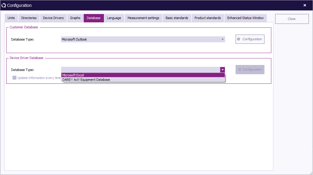
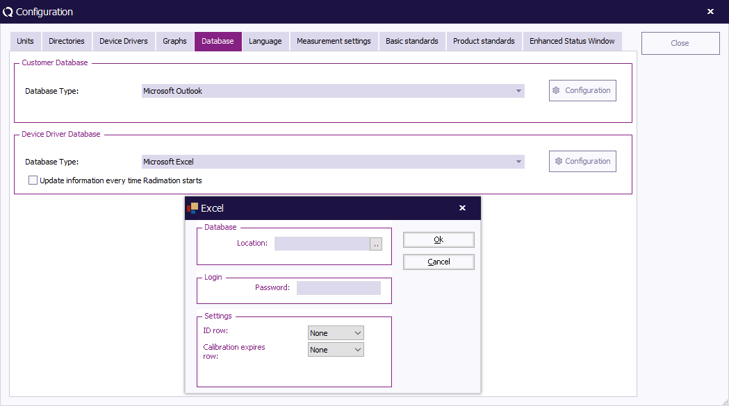
Chapter 2: Difference between revisions
No edit summary |
|||
| (419 intermediate revisions by 8 users not shown) | |||
| Line 1: | Line 1: | ||
__NOTOC__ | __NOTOC__ | ||
= Getting started = | = Getting started = | ||
Chapter 2 “Getting Started” provides information relevant to first time use of {{RadiMation}}. This includes (but is not limited to) a product overview and installation guide, as well as the configuration of some basic settings (such as passwords, users, languages and test parameters). | |||
For more (detailed) information, follow the links and references in the text, or go straight to the chapter related to your topic of interest. | |||
== Software overview == | == Software overview == | ||
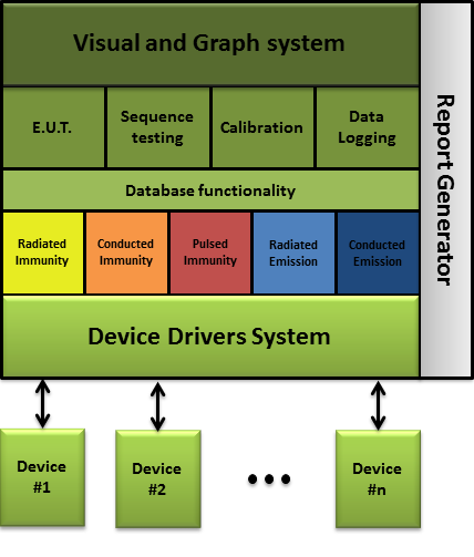
{{RadiMation}} consists of a software core and 7 complementing software modules. It can be used to perform 5 different types of EMC tests, calibrations, [[sequence]] testing and has an automatic report generation function. | |||
An overview of the {{RadiMation}} software is visible in the figure below: | |||
[[Image:Modular overview.png]] | [[Image:Modular overview.png]] | ||
The | The {{RadiMation}} Core consists of the following components: | ||
* The Visual and Graph System | * The Visual and Graph System | ||
* The EUT data management System | * The EUT data management System | ||
* Sequence Testing | * [[Sequence]] Testing | ||
* Calibration | * [[Calibration]] | ||
* Data Logging | * Data Logging | ||
* Database Functionality | * Database Functionality | ||
* The Device Driver System | * The Device Driver System | ||
Depending on the requirement, one ore more modules can be added to the {{RadiMation}} Core. | |||
The different modules are integrated in one single software package. The separate modules are: | |||
* [[Radiated immunity]] testing (RI) | |||
* [[Conducted immunity]] testing (CI) | |||
* [[Pulsed immunity]] (ESD, EFT, Surge) | |||
* [[Radiated emission]] testing (RE) | |||
* [[Conducted emission]] testing (CE) | |||
* [[Report generator]] | |||
* [[Excel Exporter]] | |||
The implementation of different modules in one software package has a number of advantages compared to other software: | |||
* Easy to use because all the modules have the same "look & feel". | |||
* Seamless data exchange between the different modules. | |||
* Calibration functionality enables an easy exchange of the calibration files. | |||
* Different types of tests can be performed, fully automatic, after each other (Sequence testing). | |||
* Fast automatic report generation, made possible by one data repository for all test data. | |||
== Conventions == | |||
{{RadiMation}} uses the Windows structure of pull down menu’s. In this manual the pull down menu’s are visualized as followed: | |||
{{Menu|File|Open|EUT}} | |||
The example above shows that, to show the file open selection window, the ''' 'File' ''' item from the menu bar should be selected first, followed by the ''' 'Open' ''' item and then the ''' 'EUT' ''' item. | |||
A screenshot of these menu items is visible below: | |||
[[Image:MenuFileOpenEUT.png]] | |||
== Hardware and software requirements == | == Hardware and software requirements == | ||
There are certain requirements that the PC(-environment, used to perform the EMC tests) needs to comply with to run [[RadiMation|{{RadiMation}}]]. | |||
=== Hardware requirements === | === Hardware requirements === | ||
The | The {{RadiMation}} software makes extensive use of data calculations, bus interactions (to control the test equipment) and screen interactions (for the use of graphs). Because of this the processor performance is very important and a dedicated PC for {{RadiMation}} is required. Running other programs on the same computer can cause compatibility problems and is not supported. Programs which are supported are the programs used by {{RadiMation}}, such as Word, Excel and MySQL. | ||
* Processor | |||
* Free RAM memory: | To use the software to its full extent the following hardware configuration is required: | ||
* Processor architecture: x64 (ARM64 is not supported) | |||
* Processor clock speed: 2 GHz minimum, > 3 GHz recommended | |||
* Free RAM memory: 2 GB minimal, > 4 GB recommended | |||
* Free hard disk space: 1 GB minimal | * Free hard disk space: 1 GB minimal | ||
* Monitor resolution: Full HD (1920 x 1080) or larger | |||
* Monitor: | |||
* IEEE card: Any GPIB Card that is supported by the [[National Instruments]] NI-488.2 Software Library | * IEEE card: Any GPIB Card that is supported by the [[National Instruments]] NI-488.2 Software Library | ||
== | ==== Memory ==== | ||
{{RadiMation}} needs a considerable amount of memory to perform at its best. We recommend that you have at least 512 MB (Mega Bytes) of free memory available, but more if possible. Free memory is defined as the amount of free RAM ''without'' having to use the swap file. Thus, not the specification of the total amount of memory that the machine has. The following steps are to help you determine the amount of free memory in your PC: | |||
{{ | |||
# Cold boot your machine from power off, not from hibernate or restart. | |||
# Determine the total amount of memory put into the computer. | |||
# Start the windows task manager and determine the commit charge. | |||
# Calculate the amount of free memory by subtracting the amount of memory of the commit charge from the amount of memory put in the computer. | |||
If the amount of free memory is less then 512 MB, there are several options to obtain more free memory. Depending on the configuration and situation, the following options are available: | |||
* Insert additional memory modules into the machine. | |||
* Remove/uninstall programs with large memory usage that do not involve measuring, for example VNC viewers. | |||
* Prevent programs from starting automatically during the booting of the computer. | |||
==== GPIB card ==== | |||
If a GPIB connection to one of the measurement equipments is used, the GPIB hardware and software needs to be installed correctly before {{RadiMation}} is installed. {{CompanyName}} is not responsible for any additional costs or delays that may occur if this card is not installed prior to the installation of {{RadiMation}}. | |||
The used GPIB card has to be supported by the [[National Instruments]] NI-488.2 software library. At least version 15.0 or higher of the NI-488.2 software should be used. {{RadiMation}} is able to use any version of [[National Instruments]] NI-488.2 which is 15.0 or higher, so it is not needed to update the NI-488.2 library as long as the installed version is supported by National Instruments and {{RadiMation}}. | |||
=== Software requirements === | |||
The {{RadiMation}} software is supported on all the Microsoft Windows, Windows Enterprise and Windows Server 2019 (or higher) operating systems that are still supported by [[Microsoft]]. The IoT variant of these operating systems are not supported. If a specific version of Microsoft Windows is still supported, can be checked on [https://docs.microsoft.com/en-us/lifecycle/products/?products=windows Microsoft Lifecycle Policy pages]. Both the 32-bit and 64-bit versions of these operating systems are supported. In order to run RadiMation it is required that the used operating system is up to date. It can result in severe delays during an installation in the case that Windows Updates are not completely updated and installed. | |||
==== Microsoft .NET framework ==== | |||
The [[Microsoft]] [https://dotnet.microsoft.com/en-us/download/dotnet-framework/net48 .NET Framework 4.8] is also required, on Windows 10 1903 and higher this is installed by default. For Windows 10 October 2018 Update (Version 1809) the .NET framework 4.8 needs to be installed manually before installing {{RadiMation}} | |||
==== Microsoft office ==== | |||
It is required to have a supported, licensed and working version of Microsoft Office Word installed on the PC. This should be at least Microsoft Word 2016 or higher, as Microsoft Word 2013 and lower has no mainstream support anymore from Microsoft. {{RadiMation}} uses Microsoft Office Word to generate and print the printouts, besides creating the reports. | |||
The {{RadiMation}} [[Report Generator|report generater]] can create reports in the following formats: | |||
* [[Microsoft Word]] | |||
* [[Microsoft Excel]] | |||
==== Installation ==== | |||
During the installation of {{RadiMation}} a network/PC administrator from the IT department must be available. This person must be able to grant rights (for one day or more) and have sufficient knowledge of the (local) network. {{CompanyName}} is not responsible for any additional costs or delays that may occurs if this support is not provided. | |||
When {{RadiMation}} is installed for the first time, it needs to be installed with administrator rights. Upgrades have no need for full rights (although rights to perform installations are required). To update {{RadiMation}} the following rights needs to be set: | |||
* Read rights to the 'C:\' drive | |||
* Full rights to the installation directory (e.g. 'C:\Program Files\Raditeq', please note that the path may be different depending on the used OS and language) | |||
== Software installation == | == Software installation == | ||
=== First time software installation === | === First time software installation === | ||
To install the | To install the {{RadiMation}} software, please download the {{RadiMation}} setup program from our download website at: https://www.raditeq.com/radimation-download/ . Once the download has been finished, the setup program can be started. The Installation Wizard will guide you through the installation process. After installation the computer must be restarted before running {{RadiMation}}. Please read [[#User rights and installation|User rights and installation]] about the user rights and information that is required for first time installation. | ||
=== Software installation on a network === | === Software installation on a network === | ||
In a network environment multiple computers are connected with each other | In a network environment multiple computers are connected with each other though a shared communication medium. This provides several advantages compared to a local installation. One of these benefits is that data can be shared between the connected computers. The {{RadiMation}} software is designed to optimally use this advantage. All the data that is used or generated by {{RadiMation}} can also be shared on the network. In most cases we recommend the use a of network configuration over a local configuration. | ||
{{Note|When {{RadiMation}} is using a network configuration the program itself will still be executed from the local computer. It is therefore neither cached nor running directly from the network.}} | |||
To | To fully use the functionality of data sharing, the configuration of {{RadiMation}} should be changed slightly. Make the necessary alterations by following the steps below: | ||
# Create a shared network directory on one of the Network Servers. Your Network Administrator can help you with this. This directory will be called <NetworkDir> from now on. | # Create a shared network directory (with the appropriate rights) on one of the Network Servers. Your Network Administrator can help you with this. This directory will be called <NetworkDir> from now on. | ||
# Create a sub-directory | # Create a drive assignment for this specific <NetworkDir>. This will avoid the use of excessive path depths. Your Network Administrator can also help you with this step. | ||
# | # Create a sub-directory with the name <Setup> in the <NetworkDir>. | ||
# Install | # Copy the {{RadiMation}} setup.exe file from the CD-ROM (or, if you downloaded {{RadiMation}}, directly from local disk) to the <Setup> directory in the <NetworkDir>. | ||
# Install {{RadiMation}} on one of the network computers. This can be done by launching the setup.exe program. Use the installation procedure as described in the previous section. | |||
# In the <NetworkDir>, create the following sub-directories: | # In the <NetworkDir>, create the following sub-directories: | ||
#* CAL_File | #* CAL_File | ||
#* CONFDVDR | |||
#* COR_File | #* COR_File | ||
#* | #* EUT_File | ||
#* LLF_File | #* LLF_File | ||
#* Printout | |||
#* RGO_File | |||
#* RGT_File | #* RGT_File | ||
#* SEQ_File | #* SEQ_File | ||
#* TSF_File | #* TSF_File | ||
# Start the installed | # Start the installed {{RadiMation}} program and open the Configuration window. On the {{ScreenElement|Directories}} tab, change the location of the {{ScreenElement|Device Driver Configuration}} directory to the CONFDVDR directory in the <NetworkDir>. (Note: do not change the other directories yet.) | ||
# Restart the RadiMation program | # Restart the {{RadiMation}} program. | ||
# Open the Configuration window again and on the {{ScreenElement|Directories} tab, change the location of all the directories to the corresponding directories in the <NetworkDir>. | # Open the Configuration window again and on the {{ScreenElement|Directories}} tab, change the location of all the other directories to the corresponding directories in the <NetworkDir>. | ||
# Restart the RadiMation program again. | # Restart the {{RadiMation}} program again. | ||
# | # The {{RadiMation}} program will use the <NetworkDir> as its main data directory from now on. | ||
# Start the Configuration of the | # Start the Configuration of the {{RadiMation}} software as described in the remaining part of this chapter. The complete configuration will be written to the <NetworkDir>. | ||
When the {{RadiMation}} software is installed on another computer in the network, the following steps can be used: | |||
# Install the {{RadiMation}} software from the <Setup> sub-directory in the <NetworkDir>. Use the installation procedure as described in the previous section. | |||
# Start the installed {{RadiMation}} program and open the Configuration window. On the {{ScreenElement|Directories}} tab, change the location of the {{ScreenElement|Device Driver Configuration}} directory to the CONFDVDR directory in the <NetworkDir>. | |||
# Restart the {{RadiMation}} program. | |||
The newly installed {{RadiMation}} will now use the already configured <NetworkDir>. | |||
The | === Automated / Silent installation === | ||
{{RadiMation}} is not provided as a .MSI file that can be used by network administrators to perform an automated installation on a lot of PC's. However {{RadiMation}} is provided as an .EXE file that does accept additional command line arguments that can be used to perform an automated silent installation. | |||
The following arguments can be specified to the {{RadiMation}} setup .EXE program: | |||
{|class="wikitable" | |||
!Argument || Purpose and explanation | |||
|- | |||
|/SP- || Disables the 'This will install ... Do you wish to continue?' prompt at the beginning of the setup | |||
|- | |||
|/SILENT || Instructs the setup program to be silent | |||
|- | |||
|/VERYSILENT || Instructs the setup program to be very silent | |||
|- | |||
|/SUPPRESSMSGBOXES || Instructs the setup to suppress message boxes | |||
|- | |||
|/LOG || Causes setup to create a log file in the user's TEMP directory | |||
|- | |||
|/LOG="filename" || Same as /LOG, except it allows to specify a fixed path/filename to use for the log file. | |||
|- | |||
|/NOCANCEL || Prevents the user from cancelling during the installation process. | |||
|- | |||
|/NORESTART || Prevents Setup from restarting the system following a successful installation, or after a Preparing to Install failure that requests a restart. | |||
|- | |||
|/DIR="x:\dirname" || Overrides the default directory name | |||
|- | |||
|/HELP || Shows a detailed explanation of all the command line parameters | |||
|} | |||
The {{RadiMation}} SETUP.EXE also contains the [[DRIVERS.EXE]] that was actual at the moment that the SETUP.EXE was build. That embedded [[DRIVERS.EXE]] will automatically be installed during the installation of the {{RadiMation}} version. If in the same directory in which the SETUP.EXE is located, also an 'AUTOINSTALLDRIVERS.EXE' is present, then that 'AUTOINSTALLDRIVERS.EXE' will be installed instead of the embedded [[DRIVERS.EXE]]. The 'AUTOINSTALLDRIVERS.EXE' can be created by just renaming the desired [[DRIVERS.EXE]] to 'AUTOINSTALLDRIVERS.EXE'. | |||
=== Installing software updates === | === Installing software updates === | ||
Software updates are | Software updates can be downloaded from the [https://www.raditeq.com/radimation-download/ {{RadiMation}} Download] page. These updates are supplied as {{RadiMation}} versions with a higher version number. | ||
Once the download of the new version has been finished, the setup program can be started. The setup program will install the new {{RadiMation}} version at the same location as the previous older, but in a separate installation folder. This will allow you to use the previously installed {{RadiMation}} version, as well as the new one. | |||
==== Installing from a network directory ==== | |||
If the already installed {{RadiMation}} version was installed from a network directory, the new setup file can be copied to the <Setup> sub-directory of the <NetworkDir>. | |||
The new {{RadiMation}} version can then be installed on each computer from that <Setup> sub-directory. This installation still has to be started manually, {{RadiMation}} will not automatically detect that a newer version is available on the network directory, and it will not automatically start the installation of the newer version. | |||
==== Updating device drivers ==== | |||
After the new {{RadiMation}} version is installed, we strongly recommend that you install the latest [[device drivers]] as well. These device drivers can be installed by starting the ‘[[DRIVERS.EXE]]’ program that can be downloaded from our [https://wiki.dare.nl/wiki/index.php/Device_drivers RadiWiki website]. | |||
The [[DRIVERS.EXE]] program will detect the different {{RadiMation}} versions installed on your PC. A dialog will start, asking you to select the {{RadiMation}} version that needs updated device drivers. Select the latest version of {{RadiMation}} that was just installed. | |||
{{ | You have successfully obtained the latest released version of {{RadiMation}} when both the software and device drivers have been updated. | ||
{{Note|We strongly advice that a you make a complete backup of all your files and directories (e.g. TSF/Sequence/Correction/Calibration and EUT) before installing a {{RadiMation}} update.}} | |||
{{Warning| '''Do ''NOT'' uninstall {{RadiMation}}!!''' This will cause removal of all user settings, TSF, sequence, calibration and correction files. This is unrecoverable.}} | |||
== User rights and installation == | == User rights and installation == | ||
For a new installation or an update, different user rights can be setup. | |||
=== New installation === | === New installation === | ||
A new installation can only be performed with administrator rights. When installed without administrator rights a successful installation is not guaranteed. | A new installation can only be performed with administrator rights. When installed without administrator rights a successful installation is not guaranteed. | ||
=== Update === | |||
To update the {{RadiMation}} software, the user must have the rights to read and write in the {{RadiMation}} folder, which is normally located in the C:\Program Files (x86)\Raditeq\ directory. | |||
=== Daily usage === | |||
For daily usage of the {{RadiMation}} software, no specific rights are needed. Every standard end-user should be able to start and use the already installed {{RadiMation}} software. | |||
== Software protection key == | |||
[[Image:Dongle-keyhanger.jpg|thumb|Software protection key]] | |||
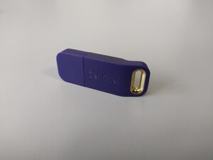
The {{RadiMation}} software is copy protected with an USB [[Software protection key]]. The USB [[Software protection key]] should be connected to the PC while a {{RadiMation}} test is running, or when the report generator or Excel Exporter is used. The USB Software protection key is not needed to open and review the test results. | |||
A network license or a floating license of the USB [[Software protection key]] is not available, and each {{RadiMation}} test PC should thus have it's own USB [[Software protection key]] physically connected to the PC. | |||
== Software configuration == | == Software configuration == | ||
In the main menu, under the configuration pull down menu, a number of standard configurations can be made. The selected and / or entered configurations will be used as default. | In the main menu, under the configuration pull down menu, a number of standard configurations can be made. The selected and/or entered configurations will be used as the default settings for future use. | ||
The next paragraphs will explain the required configurations. | |||
=== Password protection === | |||
{{RadiMation}} allows to protect a number of configurations by assigning applicable rights to an engineer, where also a login password can be configured for those engineers. | |||
* The password protection is by default turned on for the default engineer with the name: 'Administrator'. | |||
* The default password is '''Radimation'''. | |||
* Configuring and using additional engineers with different passwords is optional. | |||
* The configured engineers are stored in the {{ScreenElement|Device Driver Configuration Files}} directory, which can be configured using the menu: | |||
{{Menu|Configuration|Configuration|Directories}} | |||
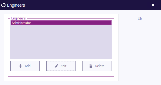
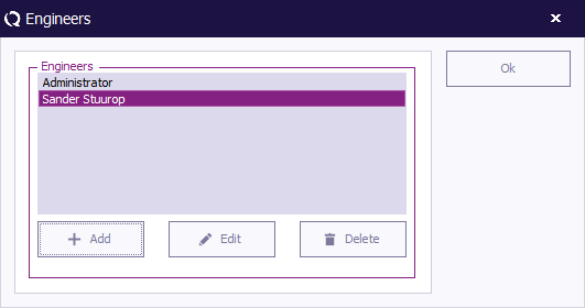
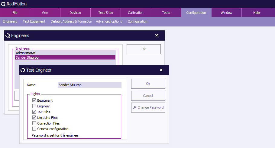
To change the password protection settings, go to the {{ScreenElement|Engineers}} window in the {{ScreenElement|Configuration}} tab. | |||
[[Image:Config engineers.png]] | |||
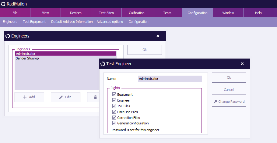
Select the {{ScreenElement|Administrator}} engineer and click {{ScreenElement|Edit}}. | |||
[[Image:Engineers admin.png]] | |||
In the {{ScreenElement|Test Engineer}} window for the 'Administrator' user, the password can be enabled, disabled or modified. | |||
The current password setting for the selected engineer is displayed at the bottom of the window. This will indicate whether a password has been ‘set’ or ‘not set’. | |||
In addition, the protection can be enabled or disabled for the following items: | |||
{{ScreenElementDescriptionStart}} | |||
{{ScreenElementDescription|Equipment|Prevents unauthorized changes to test equipment configuration.}} | |||
{{ScreenElementDescription|Engineer|Prevents unauthorized changes to test engineers configuration.}} | |||
{{ScreenElementDescription|TSF Files|Prevents unauthorized changes to [[Test Setup File]]s (TSF) files.}} | |||
{{ScreenElementDescription|Limit Line|Prevents unauthorized changes to [[Chapter 18|Limit Line File]]s (LLF) files.}} | |||
{{ScreenElementDescription|Correction File|Prevents unauthorized changes to correction files.}} | |||
{{ScreenElementDescription|General Configuration|Prevents unauthorized changes to the general configuration.}} | |||
{{ScreenElementDescriptionEnd}} | |||
To enable, disable or change the password, click {{ScreenElement|[[Change Password]]}}. | |||
[[Image:Test engineer.png]] | |||
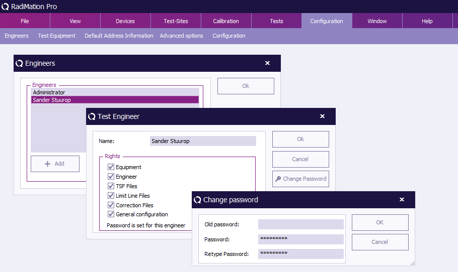
To change the password, enter the old password and the new password (twice), then click {{ScreenElement|OK}}. You will be returned to the {{ScreenElement|Test Engineer}} window. | |||
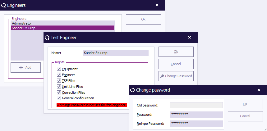
[[Image:Change password.png]] | |||
To disable the password, enter the old password and leave the other two fields empty, then click {{ScreenElement|OK}}. You will be returned to the {{ScreenElement|Test Engineer}} window. | |||
(The password indication will change to: "Warning: Password is not set for this engineer.") | |||
{{ | [[Image:Disable password.png]] | ||
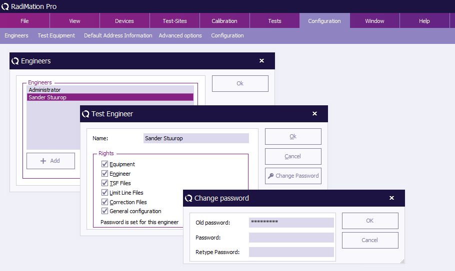
To enable the password, enter the new password (twice), then click {{ScreenElement|OK}}. You will be returned to the {{ScreenElement|Test Engineer}} window. | |||
(The password indication will change to: "Password is set for this engineer.") | |||
[[Image:Enable password.png]] | |||
To leave the {{ScreenElement|Engineers}} window, click {{ScreenElement|Ok}}. | |||
=== Test engineers === | === Test engineers === | ||
| Line 132: | Line 278: | ||
For each test, the name of the test engineer performing the current test can be entered. | For each test, the name of the test engineer performing the current test can be entered. | ||
To add, delete or edit (the names of) test engineers, go to the ''' 'Engineers' window''' in the ''' 'Configuration' tab'''. | |||
[[Image:Config engineers.png]] | |||
The Engineers window will show the current configured list of engineers. To leave the ''' 'Engineers' window''', click ''' 'OK' '''. | |||
To add a new test engineer, click ''' 'Add' '''. | |||
[[Image:Engineer add engineer.png]] | |||
Enter the name and set the rights of the new engineer, then click ''' 'OK' '''. You will be returned to the ''' 'Engineers' window'''. | |||
The new engineer will not have a protection password (yet), this can be enabled by clicking ''' '[[Change Password|Change Password]]' '''. Please read [[#Password protection|Password protection]] for more information. | |||
[[Image:Test engineer add engineer.png]] | |||
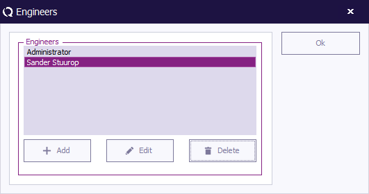
To delete a test engineer, select the engineer and click ''' 'Delete' '''. | |||
[[Image:Engineer delete engineer.png]] | |||
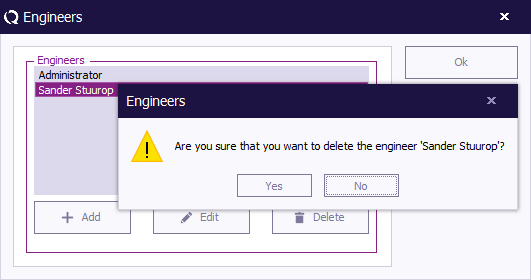
To confirm that you want to delete the engineer from the configuration list, click ''' 'Yes' '''. | |||
If you do not want to delete this engineer from the list, click ''' 'No' ''' or ''' 'Cancel' '''. You will be returned to the ''' 'Engineers' window'''. | |||
[[Image:Engineer delete engineer confirm.png]] | |||
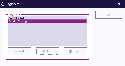
To edit the name, rights and/or password of an engineer, select the engineer and click ''' 'Edit' '''. | |||
[[Image:Engineer edit engineer.png]] | |||
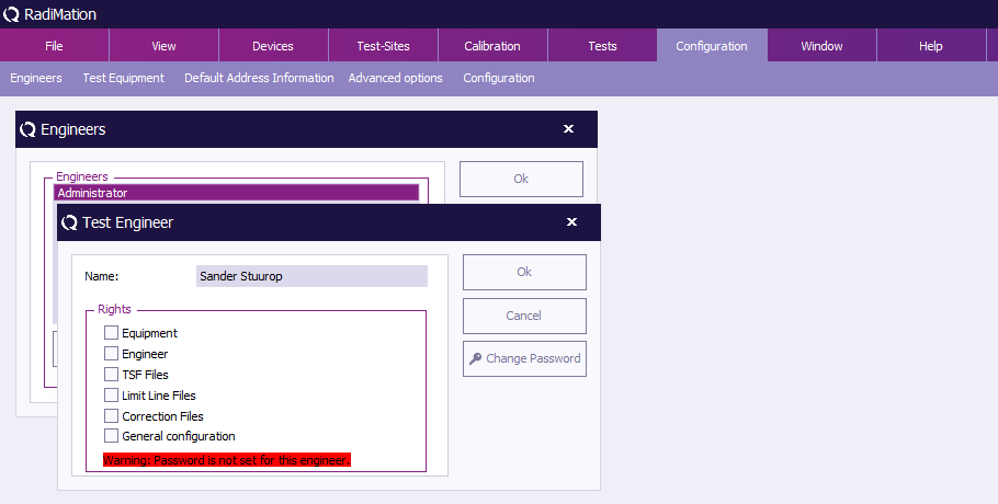
Make the desired changes in the ''' 'Test Engineer' window''' and click ''' 'OK' '''. | |||
If you want to undo or cancel your changes, click ''' 'Cancel' '''. You will be returned to the ''' 'Engineers' window'''. | |||
[[Image:Test engineer edit engineer.png]] | |||
=== Default address information configuration === | === Default address information configuration === | ||
When a new [[EUT]] file is created, the name and address information of the manufacturer, test house and client can be entered separately. | |||
In many situations one or more of this information will be the same for different [[EUT]] files (i.e.: when a test house owns the software, the test house data will always be the same). | |||
To prevent users from having to enter repetitive data input, {{RadiMation}} provides the option to set default address information for: | |||
* The default client | * The default client | ||
* The default manufacturer | * The default manufacturer | ||
* The default test site | * The default test site | ||
Data entered under | The default address information is stored in the {{ScreenElement|Device Driver Configuration Files}} directory, which can be configured using the menu: {{Menu|Configuration|Configuration|Directories}} | ||
Data entered under {{ScreenElement|Default Address Information}}, will automatically be copied and stored in the [[EUT]] file. Specifying this information is not required, however it has the benefit that address information that is always the same doesn't need to be entered over and over again in every new [[EUT]] file. | |||
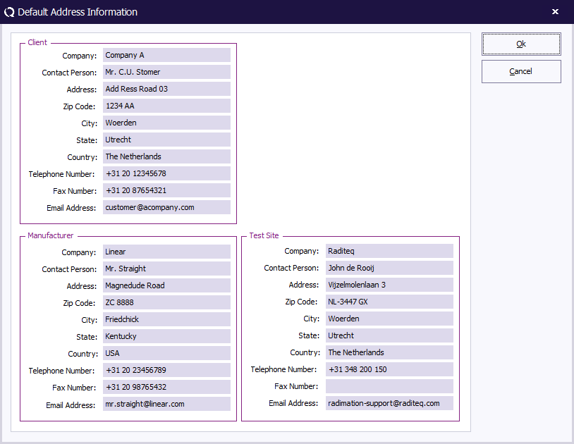
To add, modify or delete the default address information, go to the {{ScreenElement|Default Address Information}} window in the {{ScreenElement|Configuration}} tab. | |||
[[Image:Config default address information.png]] | |||
Enter the desired information as shown in the example below. | |||
{{ | To confirm the data input, click {{ScreenElement|OK}}, to cancel the data input, click {{ScreenElement|Cancel}}. The {{ScreenElement|Default Address Information}} window will close. | ||
[[Image:Default Address Information.png]] | |||
=== Default Units === | === Default Units === | ||
{{RadiMation}} allows the user to define the default units. These units are used throughout the software package and can be changed at any time during measurements and viewing. | |||
To configure the unit settings, go to the ''' 'Configuration' window''' in the ''' 'Configuration' tab'''. | |||
[[Image:Config configuration.png]] | |||
The default settings for the different units can be set in the ''' 'Units' tab'''. | |||
It is possible to define different units for different tests. The following can be selected: | |||
* Radiated Immunity | |||
* Conducted Immunity | |||
* Radiated Emission | |||
* Conducted Emission | |||
* Pulsed Immunity | |||
* Antenna Diagram | |||
* RadiCal | |||
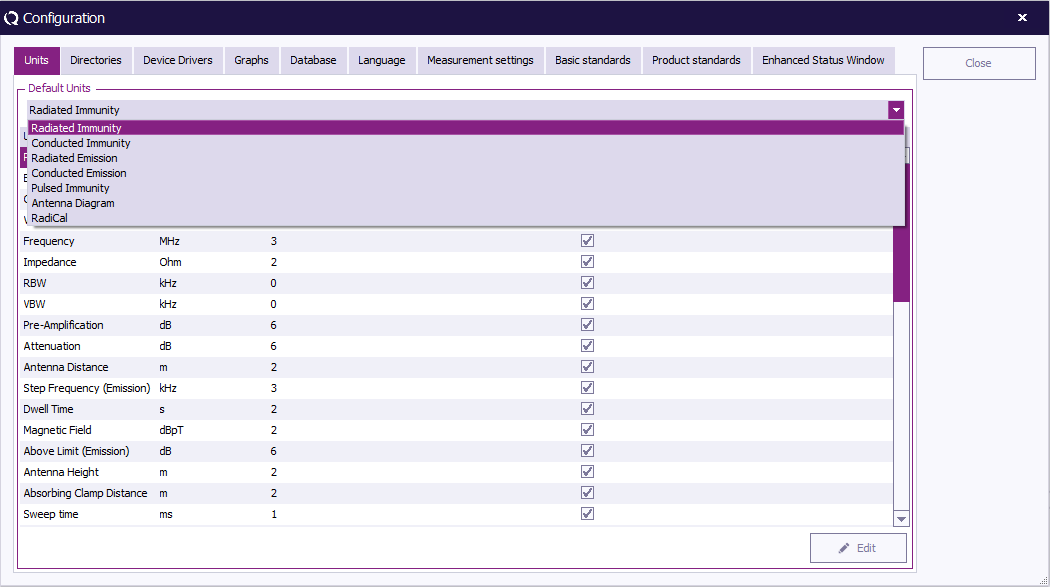
To change the settings of a unit, choose the desired test (e.g. Radiated Immunity) from the drop down menu in the ''' 'Units' tab'''. | |||
[[Image:Configuration units test selection.png]] | |||
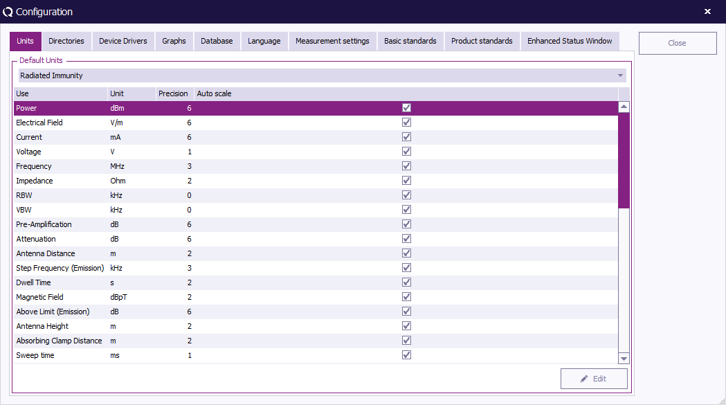
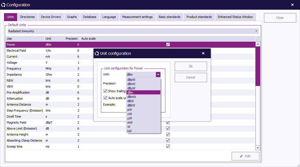
Select the measurement (e.g. Power) and click ''' 'Change'. | |||
[[Image:Configuration Units.png]] | |||
The | The ''' '{{WindowTitle|Unit configuration}}' window''' will appear, allowing you to change the parameters of the unit. | ||
To confirm your changes, click ''' 'OK' ''', to cancel your changes, click ''' 'Cancel' '''. You will be returned to the ''' 'Configuration' window'''. | |||
[[Image:Configuration units change2.png]] | |||
Click ''' 'Close' ''' to leave the ''' 'Configuration' window'''. | |||
=== Default directories configuration === | === Default directories configuration === | ||
The | The {{RadiMation}} software can use different directories to store different data file types. | ||
The location of the following file types can be specified: | |||
* Equipment Under Test Data files (*.EUT files), | * Equipment Under Test Data files (*.EUT files), | ||
| Line 178: | Line 403: | ||
* Printout files (*.DOC files). | * Printout files (*.DOC files). | ||
The different file types are described in [[Chapter 18|Chapter 18 “{{RadiMation}} file types and locations”]]. | |||
For each data type the default | |||
For each data type the default location can be entered through the configuration. The path name can link to a directory on a local or network drive. | |||
Selecting a network drive will allow you to store data (e.g. EUT data) on a computer network, making it more accessible. | |||
To modify a path name, go to the ''' 'Configuration' window''' in the ''' 'Configuration' tab'''. | |||
[[Image:Config configuration.png]] | |||
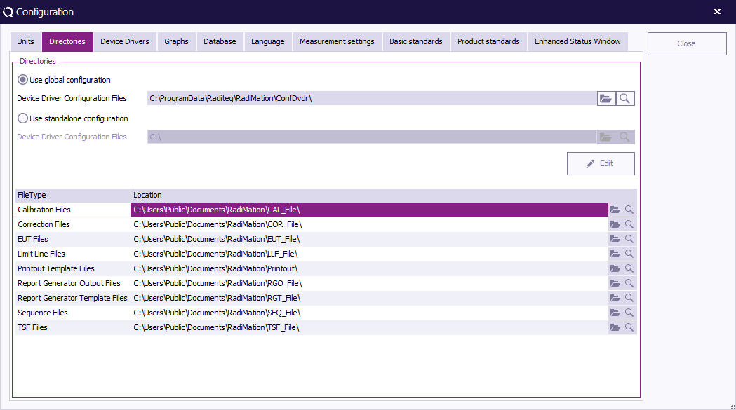
Go to the ''' 'Directories' tab''', select the directory that you wish to change and click ''' 'Change' '''. | |||
[[Image:Configuration Directories.png]] | |||
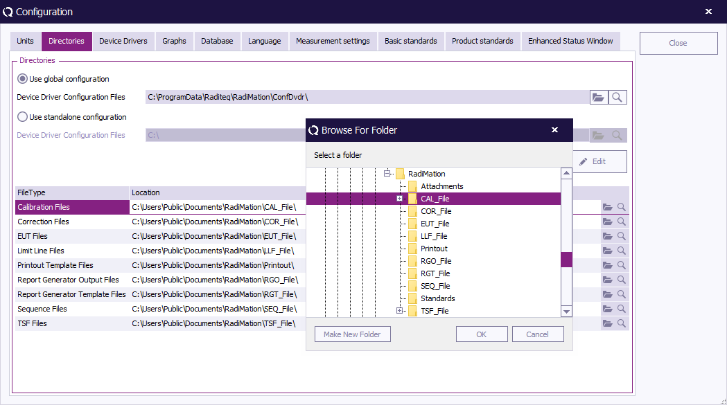
The ''' 'Browse For Folder' window''' will appear, allowing you to select (or make) a new folder in your directory. | |||
To confirm your change, click ''' 'OK' ''', to cancel your change, click ''' 'Cancel' '''. You will be returned to the ''' 'Configuration' window'''. | |||
[[Image:Browse Calibration File Directory.png]] | |||
Click ''' 'Close' ''' to leave the ''' 'Configuration' window'''. | |||
=== Device driver configuration === | === Device driver configuration === | ||
Device drivers | Device drivers let your software know which equipment has to be used and controlled during EMC tests. | ||
In {{RadiMation}}, the device drivers only need to be configured to the customer requirements once. | |||
During the configuration of the device driver, information such as the IEEE address or RS232 COM-port has to be entered. | |||
You can configure the device drivers in the ''' 'Configuration' window'''. | |||
This window can be accessed in one of two ways, either through the ''' 'Configuration' tab''' or through the ''' 'Devices' tab'''. | |||
[[Image:Config configuration.png]] | |||
[[Image:Device configure.png]] | |||
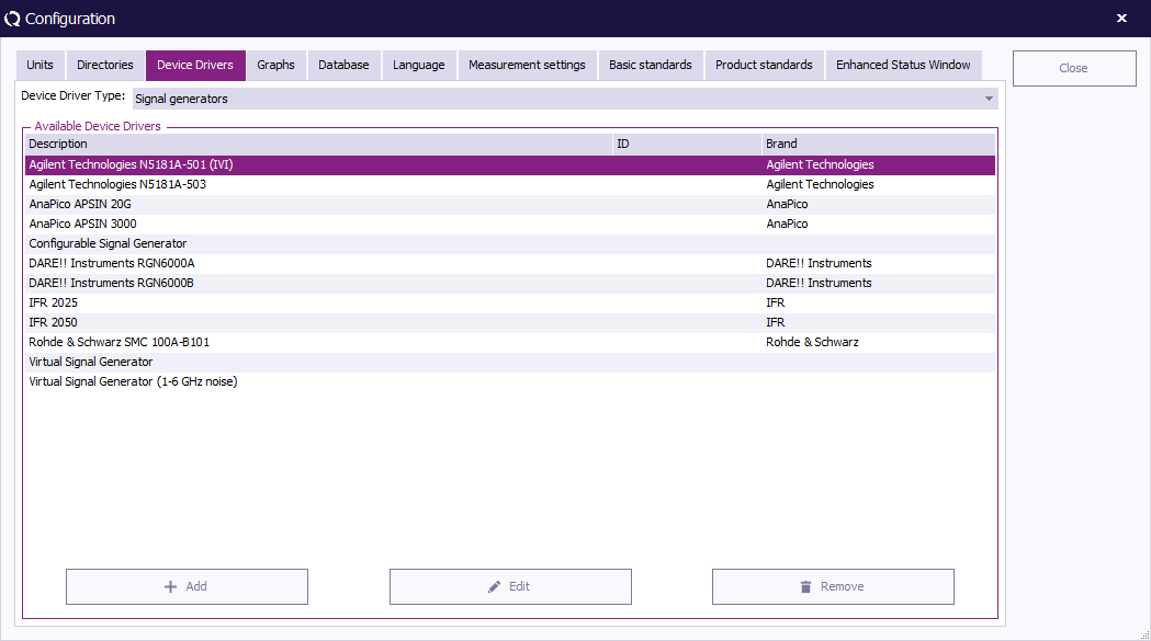
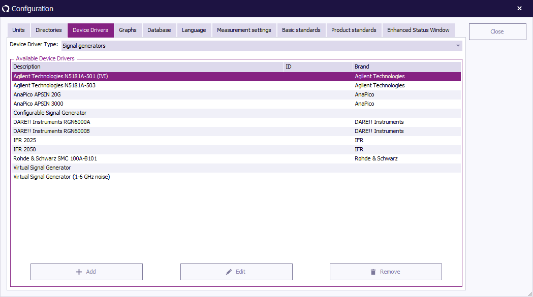
To configure a device driver, go to the ''' 'Device Drivers' tab''' in the ''' 'Configuration' window'''. | |||
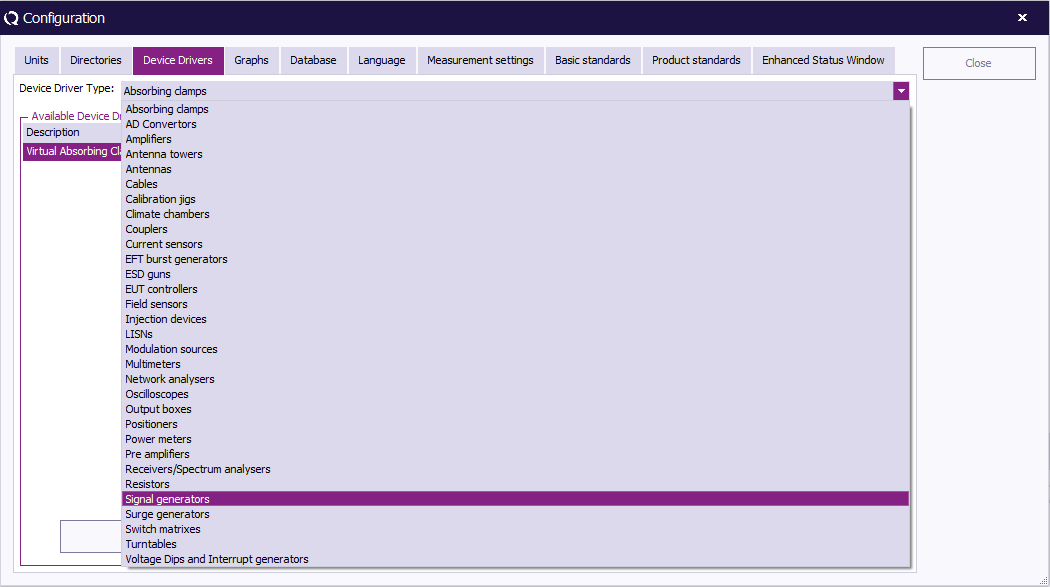
Select the desired ''' '[[Device Types|Device Driver Type]]' ''' from the drop-down menu (e.g. Signal Generator). The available drivers for that type will be shown. | |||
[[Image:Device driver type.png]] | |||
To create a new {{RadiMation}} device driver, select the desired ''' 'Device Driver Type' ''' (e.g. Signal Generator) and click ''' 'Add' '''. | |||
[[Image:Device driver add.png]] | |||
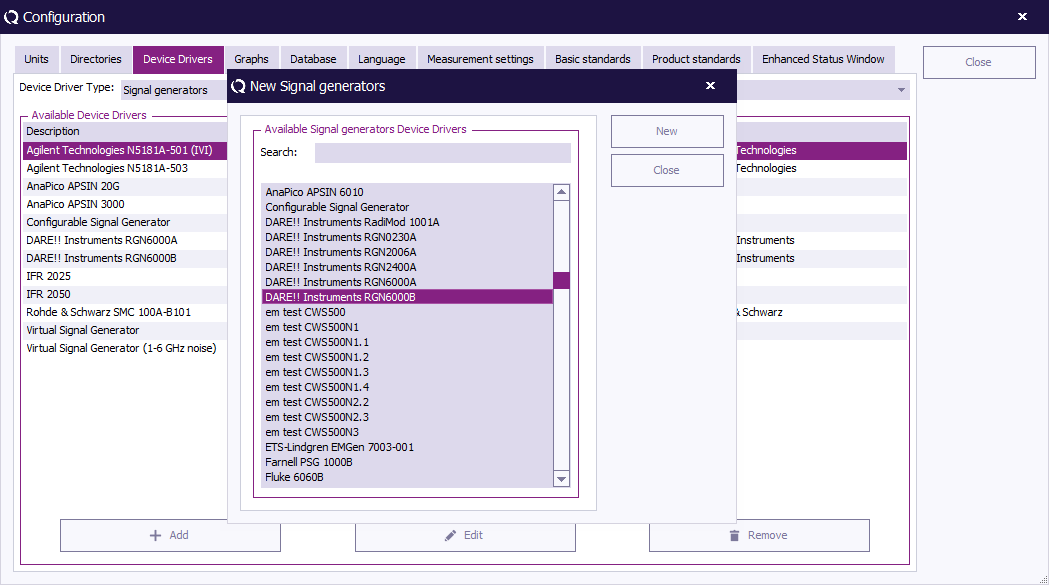
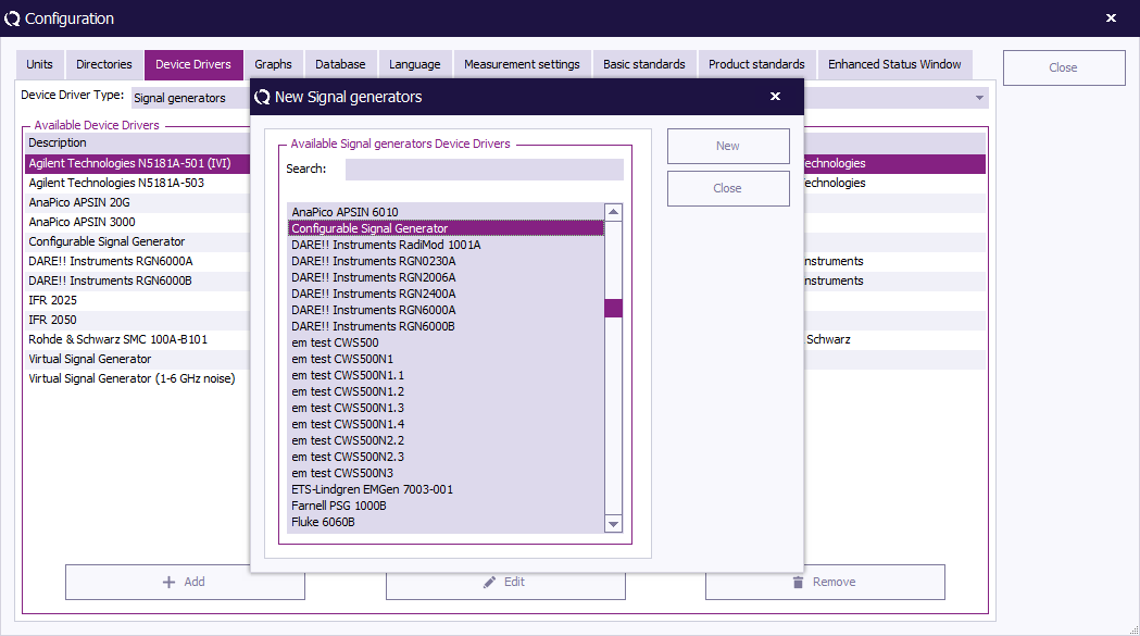
Select a new device driver (in the scroll menu or through the search function) and click ''' 'New' '''. | |||
To cancel your selection and return to the ''' 'Configuration' window''', click ''' 'Close' '''. | |||
[[Image:New signal generators.png]] | |||
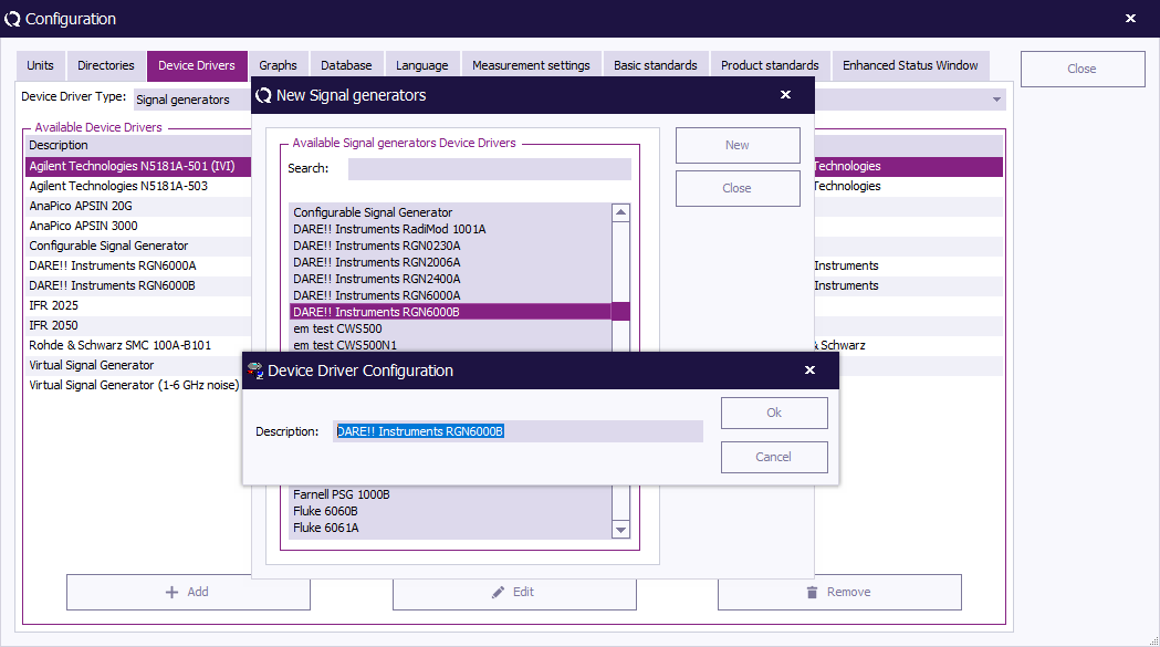
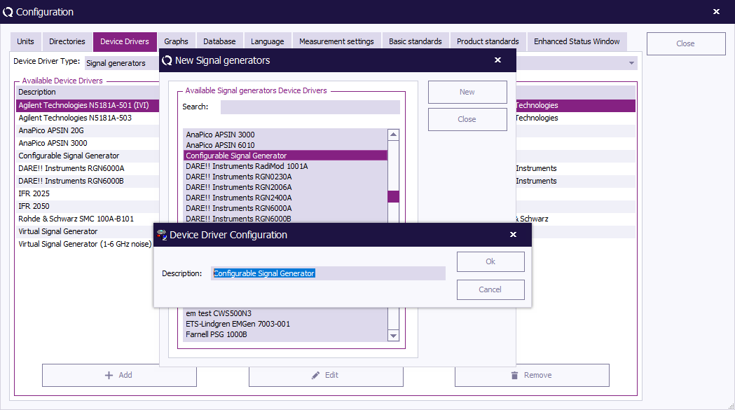
The name/description of the chosen device driver can be changed in the ''' 'Device Driver Configuration' window'''. | |||
To confirm your changes (or the provided description), click ''' 'OK' ''', the ''' 'Device Driver Settings' window''' will appear. | |||
To cancel your changes, click ''' 'Cancel' '''. You will be returned to the previous window (e.g. New Signal generators). | |||
[[Image:Device driver configuration.png]] | |||
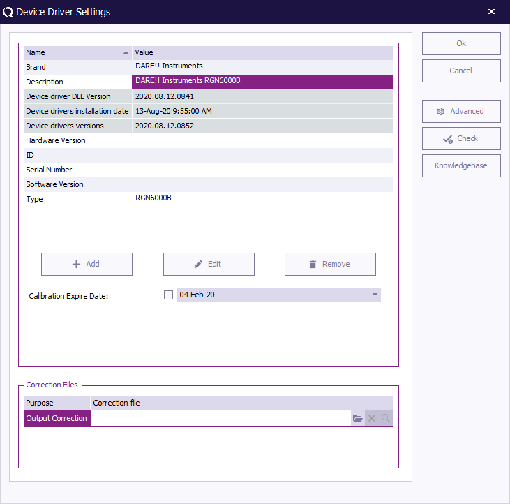
The ''' 'Device Driver Settings' window''' will appear with information on the selected device driver. In this window information can be added, edited and removed. | |||
To confirm the settings, click ''' 'OK' ''', to cancel your changes, click ''' 'Cancel' '''. You will be returned to the ''' 'Configuration' window'''. | |||
More detailed device driver settings are described in the paragraph "Device Driver settings" in [[Chapter 14]]. | |||
[[Image:Device driver settings.png]] | |||
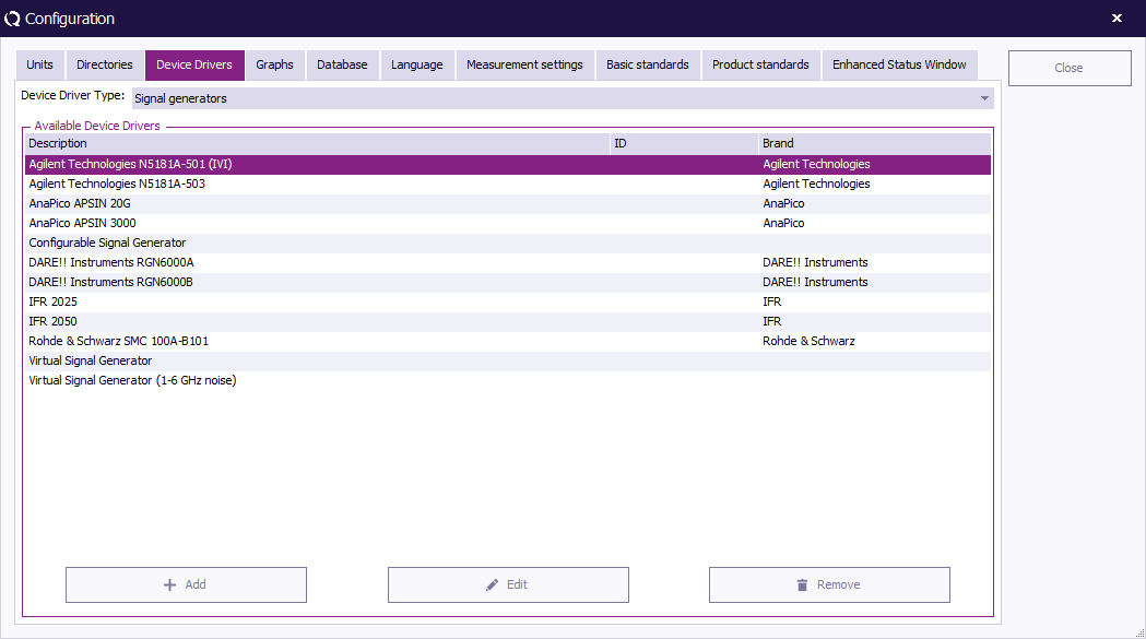
To edit an existing device driver, select the desired (device driver) type and device driver, then click ''' 'Edit' '''. (The ''' 'Device Driver Settings' window''' will appear.) | |||
[[Image:Device driver edit.png]] | |||
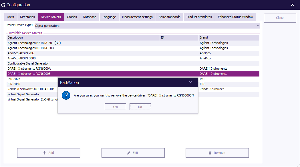
To remove an existing device driver, select the desired (device driver) type and device driver, then click ''' 'Remove' '''. | |||
[[Image:Device driver remove.png]] | |||
A confirmation window will appear. To remove the selected device driver, click ''' 'Yes' ''', to cancel, click ''' 'No' '''. You will be returned to the ''' 'Configuration' window'''. | |||
[[Image:Device driver remove2.png]] | |||
Click ''' 'Close' ''' to leave the ''' 'Configuration' window'''. | |||
=== Graphics configuration === | |||
{{RadiMation}} allows you to customize the way graphics are displayed on your screen. | |||
To configure the style of the shown graphs, go to the ''' 'Configuration' window''' in the ''' 'Configuration' tab'''. | |||
[[Image:Config configuration.png]] | |||
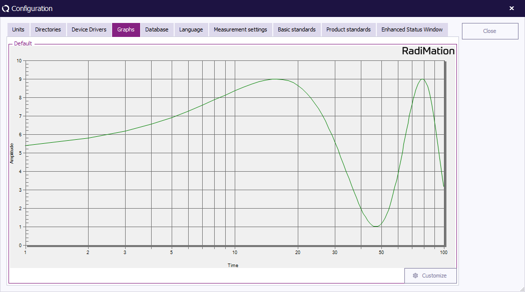
An example graph is shown in the ''' 'Graphs' tab''' that is created with the current settings. To change these graph settings, click ''' 'Customize' '''. | |||
[[Image:Configuration Graphs.png]] | |||
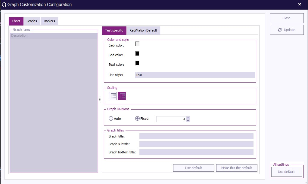
The | The '{{WindowTitle|Graph Customization Configuration}}' '''window''' contains three tabs; ''' 'Chart' ''', ''' 'Graph' ''' and ''' 'Markings' '''. | ||
The ''' 'Chart' tab''' contains the settings related to the overall graph and can be used to determine the colours, layout and titles. | |||
The ''' 'Graph' tab''' contains the settings related to the graph lines shown in the graph and can be used to determine the colours, scaling and layout of each and every shown graph line. | |||
The ''' 'Markers' tab''' contains the settings related to the markers on the graph and can be used to determine the colours, style and scaling of each and every shown marker. | |||
[[Image:GraphCustomization Chart.png]] | |||
To change the graph settings, select a graph (component) in the left section of the window, then make the desired changes in the right section of the window. | |||
Click ''' 'Update' ''' to update the graph settings without closing the '{{WindowTitle|Graph Customization Configuration}}' '''window'''. This will allow you to see the effect of the new settings and make additional changes. | |||
Click ''' 'Close' ''' to update (and save) the graph settings and close the '{{WindowTitle|Graph Customization Configuration}}' '''window'''. You will be returned to the ''' 'Configuration' window'''. | |||
The selected settings in the '{{WindowTitle|Graph Customization Configuration}}' '''window''' are used as the {{RadiMation}} default settings. It is still possible to overrule these settings for individual tests to more specific settings. | |||
Click ''' 'Restore factory default' ''' to return to the factory settings. | |||
=== Database Configuration === | |||
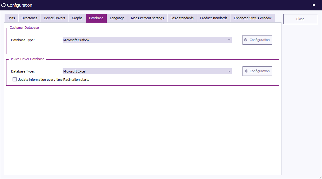
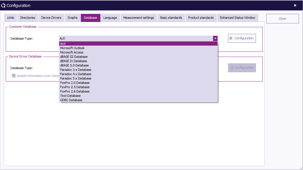
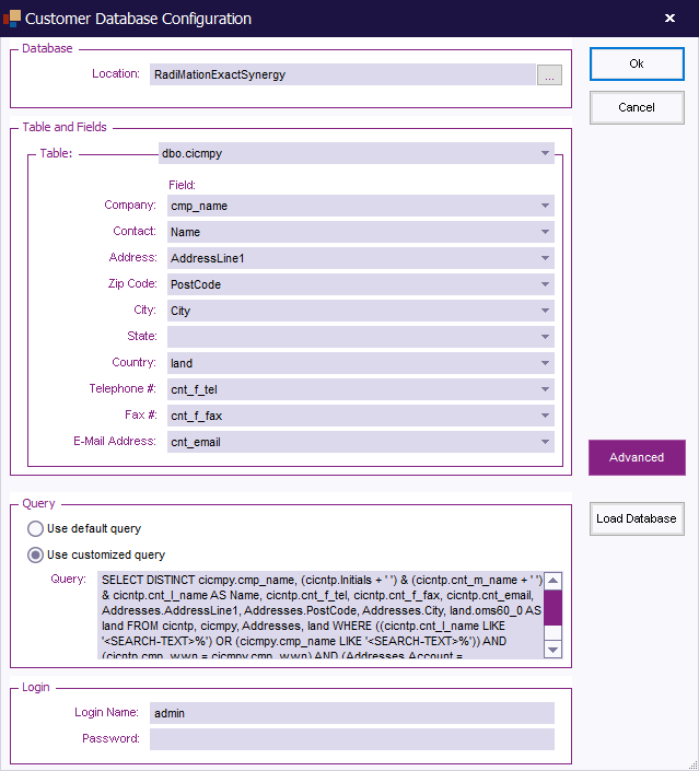
{{:Customer database}} | |||
=== Language Selection === | === Language Selection === | ||
{{RadiMation}} supports multi-language use. This means that the software package can be operated in several language. | |||
In addition, the multi- language support allows for easy translation from English to most other languages. | |||
Please contact your local reseller for the availability of your required language driver. | |||
The default language of {{RadiMation}} is English. | |||
To change the language settings, go to the ''' 'Configuration' window''' in the ''' 'Configuration' tab'''. | |||
[[Image:Config configuration.png]] | |||
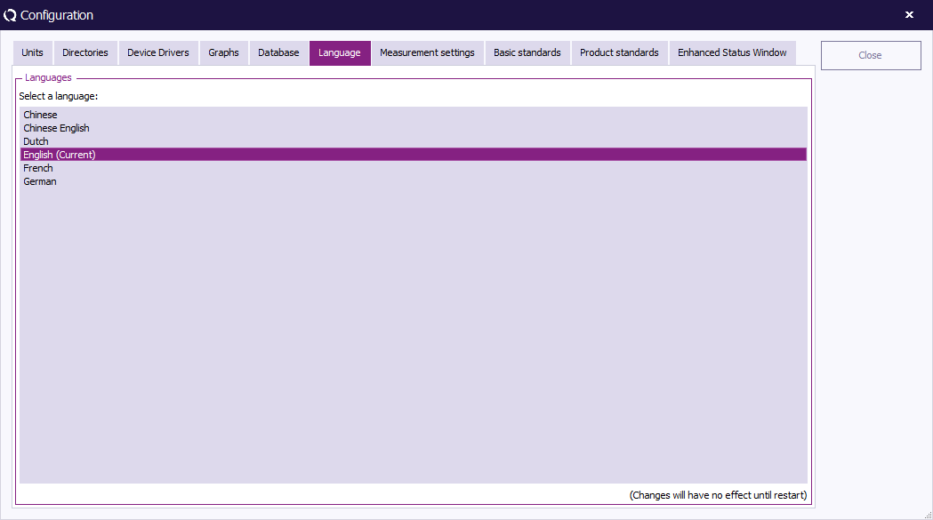
Go to the ''' 'Language' tab'''. The current language setting is marked with the text '''(current)'''. | |||
[[Image:Configuration Language.png]] | |||
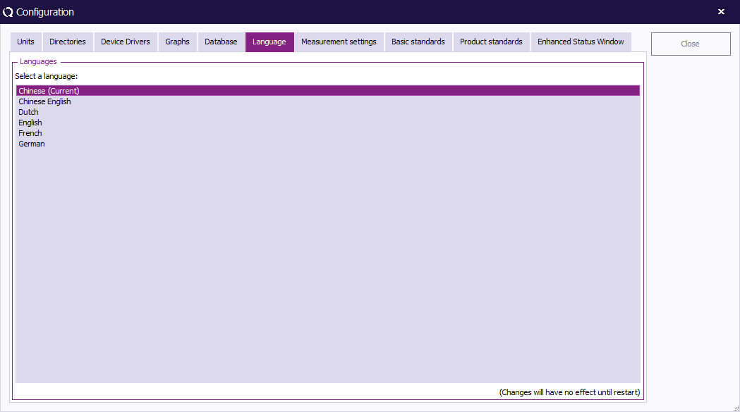
To change the language setting, select one of the other languages, click ''' 'Close' ''' (to leave the ''' 'Configuration' window''') and restart {{RadiMation}}. | |||
The selected language will only be active after {{RadiMation}} is restarted. | |||
[[Image:Configuration language2.png]] | |||
{{Note|Not all languages are currently available. Please contact your local reseller for language availability.}} | |||
=== Product Standard === | === Product Standard === | ||
==== Introduction ==== | ==== Introduction ==== | ||
Product Standards describe | Product Standards describe the requirements (e.g. dimensional, technical, etc.) and the methods of testing (as well as grading, marking, etc.) of a product. | ||
The objective of these standards is to define and impose 'standards' that will ensure that the product in question will not represent harm or hazard to consumers. | |||
Because the standards with regards to product testing can be relevant to {{RadiMation}} users, {{RadiMation}} offers the possibility to add this documentation to your configuration. | |||
There are many Product Standards for individual products and product types. These, in turn, often refer to multiple Basic Standards. | |||
Where a Product Standard describes all the tests that should be performed on a EUT, a Basic Standard only describes one single test. | |||
For example: | |||
The Product Standard for product X describes four different requirements/tests that the product needs to comply with. | |||
These four tests are described in four Basic Standards, where each basic standard describes the requirements for one test. | |||
Basic Standards can also be added to {{RadiMation}}. | |||
In addition, one single Technical Setup File (TSF) can be generated for each Basic Standard, configured to perform the test as described in the standard. | |||
==== Adding a Product Standard ==== | ==== Adding a Product Standard ==== | ||
To add a Product Standard to {{RadiMation}}, go to the ''' 'Configuration' window''' in the ''' 'Configuration' tab'''. | |||
[[Image:Config configuration.png]] | |||
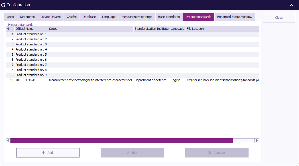
Select the ''' 'Product standards' tab''' and click ''' 'Add' '''. | |||
(To edit a Product Standard, select the standard and click ''' 'Edit' '''. To remove a Product Standard, select the standard and click ''' 'Remove' '''.) | |||
[[Image:Configuration ProductStandards.png]] | |||
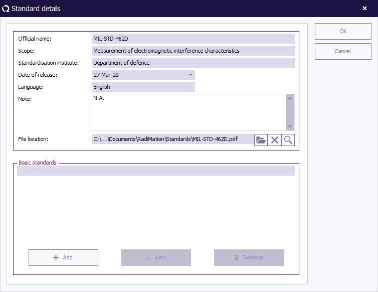
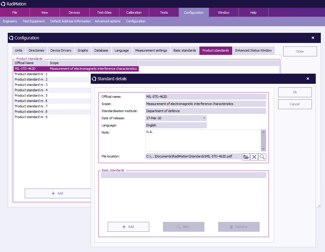
Insert the required information in the ''' 'Standard details' window''' (as visible in the example below). | |||
Please note that the '''Official name''' can only be inserted the first time and has to be unique. | |||
In addition, it is possible to link a file to the standard in the '''File location''' field. For example a PDF, DOC or HTML file that describes the standard. | |||
{{RadiMation}} will open the file (with the default reader for this file type) when the engineer selects the magnifying glass button next to that field. | |||
To confirm your data input, click ''' 'OK' ''', to cancel your input, click ''' 'Cancel' '''. You will be returned to the ''' 'Configuration' window'''. | |||
[[Image:Product standard details.png]] | |||
==== Add(ing) Basic Standard(s) ==== | ==== Add(ing) Basic Standard(s) ==== | ||
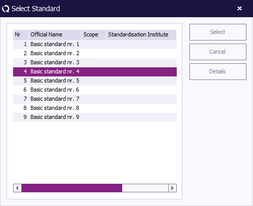
To add a Basic Standard to the product standard, click ''' 'Add' '''. The ''' 'Select Standard' window''' will appear. | |||
Select one or more Basic Standards (hold the ‘Ctrl’ key to select multiple standards) and click ''' 'Select' '''. | |||
To cancel your selection, click ''' 'Cancel' '''. You will be returned to the ''' 'Standard details' window'''. | |||
To see the details of a Basic Standard, double click the standard or click ‘Details’. | |||
[[Image:Select basic standard.png]] | |||
{{Note|When a product standard is selected or added in the ''' 'EUT' window''', the data of that standard is copied into the EUT Document. At that moment a copy of the data of the standard from the configuration is made. This means that, if the configuration of a standard in the ''' 'Configuration' window''' of {{RadiMation}} is changed, the data in the EUT file will still have the old data of the standard!!! This is as it should be, because this is the information of the standard that is used at the time that the EUT was tested.}} | |||
=== Basic Standard === | === Basic Standard === | ||
To add a Basic Standard to {{RadiMation}}, go to the ''' 'Configuration' window''' in the ''' 'Configuration' tab'''. | |||
[[Image:Config configuration.png]] | |||
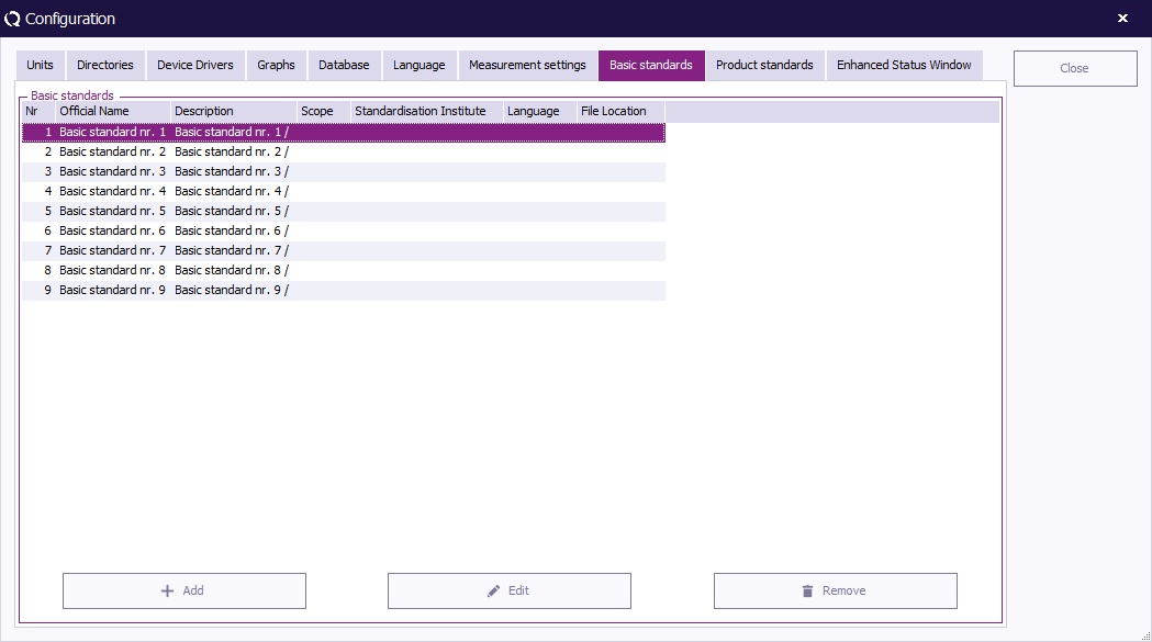
Select the ''' 'Basic standards' tab''' and click ''' 'Add' '''. | |||
(To edit a Basic Standard, select the standard and click ''' 'Edit' '''. To remove a Basic Standard, select the standard and click ''' 'Remove' '''. | |||
Please note that removing a Basic Standard from the list will also remove any references of this standard entered in the Product Standards.) | |||
[[Image:Configuration_BasicStandards.png]] | |||
Insert the required information in the ''' 'Standard details' window''' (as visible in the example below). | |||
Please note that the '''Official name''' can only be inserted the first time and has to be unique. | |||
In addition, it is possible to link a file to the standard in the '''File location''' field. For example a PDF, DOC or HTML file that describes the standard. | |||
{{RadiMation}} will open the file (with the default reader for this file type) when the engineer selects the magnifying glass button next to that field. | |||
To confirm your data input, click ''' 'OK' ''', to cancel your input, click ''' 'Cancel' '''. You will be returned to the ''' 'Configuration' window'''. | |||
[[Image:Basic standard details.png]] | |||
=== Test equipment list configuration === | === Test equipment list configuration === | ||
The test equipment configuration contains a list of all test equipment | The test equipment configuration contains a list of all the test equipment used during a test. The software uses this list to determine which device drivers should be used to control the test equipment. {{RadiMation}} allows you to configure specific test equipment lists for each type of test as well as different test equipment lists for the same type of tests. (This can be useful if you have, for example, more than one signal generator to perform conducted immunity tests with). | ||
In the | |||
In the ''' 'Test Equipment' window''' a set of test equipment will be selected. When a calibration file is generated, {{RadiMation}} will record this test equipment configuration together with the calibration data. When a substitution test is started, the test equipment selected for the substitution test will be compared with the test equipment used (as recorded) during the calibration test. If the equipment does not match, an error message will be displayed. | |||
The error message window will ask you to abort the test or to ignore the error message and continue the test with different test equipment. To achieve maximum accuracy, the same test equipment should be used (whenever possible) during both the calibration and the substitution tests. | |||
To add, modify or delete test equipment lists, go to the ''' 'Test Equipment' window''' in the ''' 'Configuration' tab'''. | |||
[[Image:Config test equipment.png]] | |||
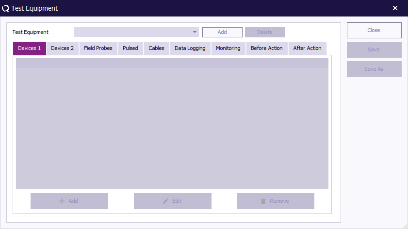
If no test equipment has been added to {{RadiMation}}, click the ''' 'Add' ''' button in the top of the window. | |||
[[Image:Test equipment.png]] | |||
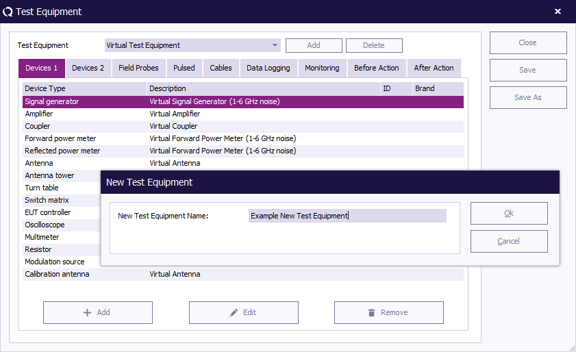
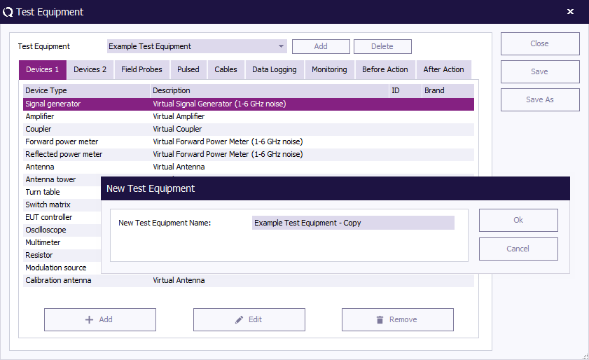
Enter a name for the new test equipment in the ''' 'New Test Equipment' window''' (e.g. Example Test Equipment). | |||
Click ''' 'OK' ''' to confirm the name of the new test equipment, or click ''' 'Cancel' ''' to cancel the new name. You will be returned to the ''' 'Test Equipment' window'''. | |||
[[Image:New test equipment.png]] | |||
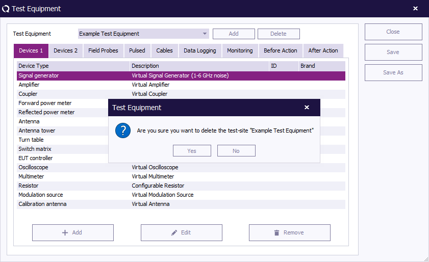
To delete a test equipment from {{RadiMation}}, select the '''Test Equipment''' from the pull down menu and click the ''' 'Delete' button''' in the top of the window. A confirmation window will appear. | |||
Click ''' 'Yes' ''' to remove the device from the list, click ''' 'Cancel' ''' to cancel. You will be returned to the ''' 'Test Equipment' window'''. | |||
[[Image:Delete test equipment.png]] | |||
To configure the equipment of a test, select the desired '''Test Equipment''' from the pull down menu (e.g. Example Test Equipment). | |||
Specify the equipment for the test by adding, editing and/or removing devices. | |||
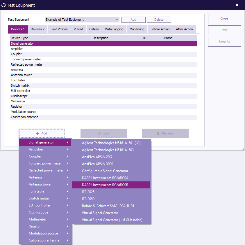
To add a device, click ''' 'Add' ''' (at the bottom left of the window), a menu will open below the button to show the available devices for each Device Type. | |||
[[Image:Test equipment add device 1.png]] | |||
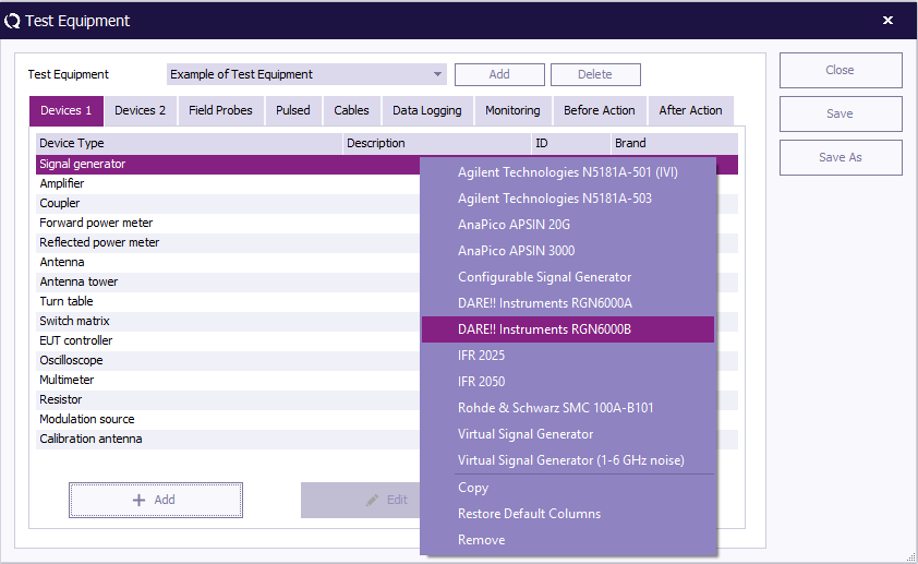
Another way to add a device is to click the desired '''Device Type''' in the ''' 'Test Equipment' overview'''. | |||
A menu will open (at your mouse point) with the available devices for that Device Type. | |||
Select and click on the desired device. The device will then appear in the equipment overview. | |||
[[Image:Test equipment add device 2.png]] | |||
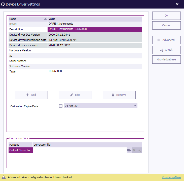
To edit a device, select the device and click ''' 'Edit' '''. The '''Device Driver Settings''' window will appear. | |||
Edit the settings as desired. To confirm your changes, click ''' 'OK' ''', to cancel your changes, click ''' 'Cancel' '''. You will be returned to the ''' 'Test Equipment' window'''. | |||
[[Image:Test equipment device driver settings.png]] | |||
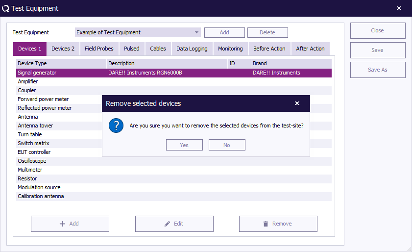
To remove a device, select the device and click ''' 'Remove' '''. A confirmation window will appear. | |||
Click ''' 'Yes' ''' to remove the device from the list, click ''' 'Cancel' ''' to cancel. You will be returned to the ''' 'Test Equipment' window'''. | |||
[[Image:Test equipment remove selected devices.png]] | |||
To | To save the changes made in the test equipment list, click ''' 'Save' ''' (you will remain in the ''' 'Test Equipment' window'''). | ||
To save the test equipment list under a new name, click ''' 'Save As' '''. | |||
Enter a new name for the test equipment in the ''' 'New Test Equipment' window''' (e.g. Example Test Equipment 2). | |||
Click ''' 'OK' ''' to confirm the name of the new test equipment, or click ''' 'Cancel' ''' to cancel the new name. You will be returned to the ''' 'Test Equipment' window'''. | |||
[[Image:Test equipment save as.png]] | |||
To close the ''' 'Test Equipment' window''', click ''' 'Close' '''. | |||
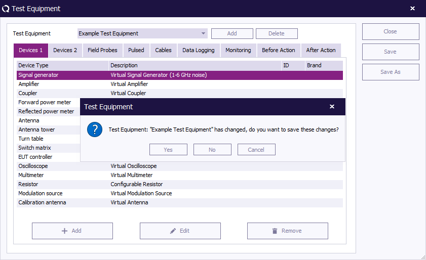
If you have not saved the changes to the test equipment list, a dedicated window will appear asking you to save these changes. | |||
To save the changes, click ''' 'Yes' ''', to not save the changes, click ''' 'No' '''. The ''' 'Test Equipment' window''' will close. | |||
[[Image:Test equipment close.png]] | |||
== User configurable device drivers == | == User configurable device drivers == | ||
{{RadiMation}} allows users to create their own device drivers for test equipment (in addition to the standard device drivers). The so called ‘user configurable device drivers’. | |||
The option to set up a user configurable device driver is available for nearly all types of test equipment. Please note that this option is not available for spectrum analyzers and measurement receivers. The complexity (and differences between suppliers) of these devices is too high. | |||
To make your own device driver, go to the ''' 'Configuration' window''' in the ''' 'Configuration' tab'''. | |||
[[Image:Config configuration.png]] | |||
Go to the ''' 'Device Drivers' tab''' and select the required '''Device Driver Type''' from the pull down menu (e.g. Signal generators), then click ''' 'Add' '''. | |||
Passive equipment such as | [[Image:Device driver add.png]] | ||
Select the '''Configurable driver''' (e.g. the Configurable Signal Generator) and click ''' 'New' '''. | |||
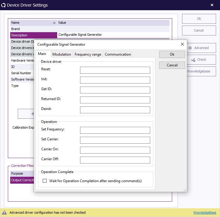
[[Image:Configurable signal generator.png]] | |||
Enter a description for the device driver (e.g. the type number of the generator) and click ''' 'OK' ''', the ''' 'Device Driver Settings' window''' will appear. | |||
To cancel your changes, click ''' 'Cancel' '''. You will be returned to the previous window (e.g. New Signal generators). | |||
[[Image:Device driver configuration2.png]] | |||
Edit he information about your ‘user configurable device driver’ in the ''' 'Device Driver Settings' window'''. | |||
Click ''' 'Advanced' ''' and enter the required control commands for the device in the tabs of the dedicated window. | |||
After the commands are entered the device driver is ready for use. Please refer to the operating manual of the equipment for the required commands. | |||
[[Image:Configurable signal generator edit.png]] | |||
To confirm the advanced settings, click ''' 'OK' ''', to cancel your changes, click ''' 'Cancel' '''. You will be returned to the ''' 'Device Driver Settings' window'''. | |||
To confirm your (final) settings, click ''' 'OK' ''', to cancel your changes, click ''' 'Cancel' '''. You will be returned to the ''' 'Configuration' window'''. | |||
Your new ‘user configurable device driver’ is now visible on the '''Available Device Drivers''' list in the ''' 'Configuration' window''' and can be used as any other device driver (by selecting it in the Equipment list). | |||
{{Note|Passive equipment, such as antennas, current probes, cables etc., also need a device driver. This is required because {{RadiMation}} has to know a number of parameters for these devices. Among others the following information is relevant: | |||
* Frequency range | * Frequency range | ||
* Maximum input power | * Maximum input power | ||
* The report generator needs to know which equipment is used during a test | * The report generator needs to know which equipment is used during a test | ||
* Correction files for these devices | * Correction files for these devices | ||
}} | |||
== EUT files == | |||
During the development of {{RadiMation}} it became clear to us that, not the EMC tests, but the Equipment Under Test (EUT) played the central role in EMC automation software. | |||
Because of this {{RadiMation}} requires that the EUT must be defined prior to any test. Defining a EUT consists of; creating a new EUT file and specifying the EUT, client and producer information. | |||
After a EUT has been defined, a test window can be opened (from the ‘Test’ menu) and a test can be started. Different types of tests can be performed from the same EUT window. All the test data for the EUT will be stored in the same EUT file. | |||
When, at a later time, tests are to be performed on the same EUT, the old EUT file can be opened and the new test results can be stored under this (old) EUT window. | |||
This allows test data from different tests, using different sets of test equipment, performed at different times and even at different locations, (regarding one EUT), to be stored in one clear EUT file. | |||
Make sure that a network is used to store all the test data when performing tests at different locations. | |||
=== Creating a new EUT file === | === Creating a new EUT file === | ||
To perform test(s) on a new device, start by creating a new EUT file. Select ''' 'File' , 'New' , 'EUT' ''' or press ''' 'Ctrl+E' '''. | |||
{{ | |||
[[Image:File new eut.png]] | |||
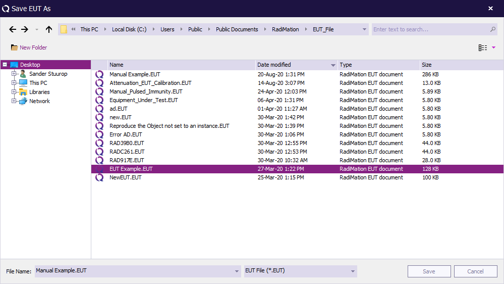
{{RadiMation}} will ask you to specify and save a file name for this new EUT file. Name the EUT file and click ''' 'Save' '''. | |||
(All the test data for this EUT will be stored under this EUT file name.) The ''' 'EUT' window''' will open. | |||
[[Image:Save eut as.png]] | |||
=== Opening an existing EUT file === | === Opening an existing EUT file === | ||
To perform test(s) on a previously tested device, open the existing EUT file for that device. Select ''' 'File' , 'Open' , 'EUT' '''. | |||
{{ | |||
[[Image:File open eut.png]] | |||
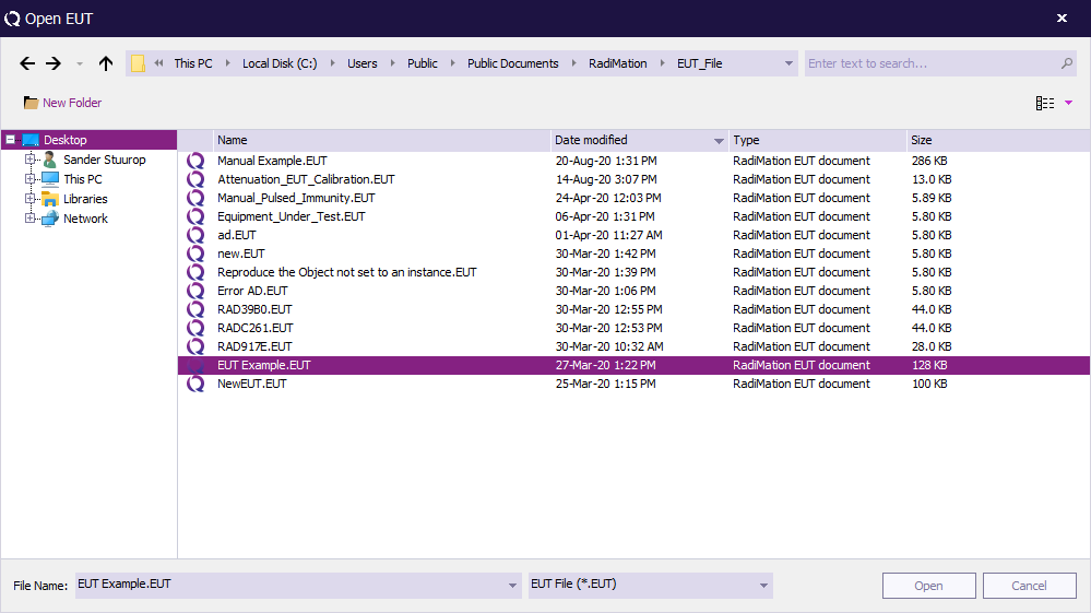
{{RadiMation}} will ask you to specify and open an existing EUT file. Select the desired EUT file and click ''' 'Open' '''. | |||
(The new test data will be added to the already existing EUT file.) | |||
[[Image:Open eut.png]] | |||
=== EUT window overview === | |||
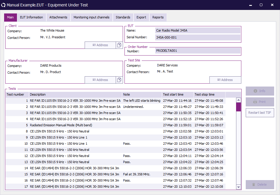
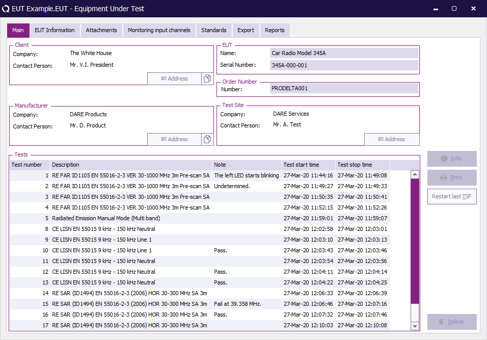
After performing a number of test the ''' 'EUT' window''' will look something like the example shown below. | |||
[[Image:Equipment under test example.png]] | |||
The ''' 'EUT' window''' contains five tabs; 'Main', 'EUT Information', 'Monitoring input channels', 'Standards' and 'Reports'. | |||
*The ''' 'Main' tab''' consists of six areas where Client, Manufacturer, EUT, Order Number, Test Site and Test information can be found and specified. | |||
*The ''' 'EUT information' tab''' consists of two areas; EUT and Cables. Here (more detailed) EUT information can be specified. This includes the cables that are connected to the EUT. | |||
The | *The ''' 'Monitoring input channels' tab''' consists of two areas that can be used to monitor the input channels and setup short cut keys (that can be used during measurements). | ||
*The ''' 'Standards' tab''' consists of two areas; Product Standards and Basic Standards. Standards related to the EUT can be added in these fields. (Documentation for standards can be added to {{RadiMation}} in the 'Product standards' and 'Basic standards' tabs of the 'Configuration' window.) | |||
*The ''' 'Reports' tab''' can be used to generate reports with the configured report generator, export reports to a spread sheet program and print detailed EUT information. | |||
More information about the content of these tabs can be found in [[Chapter 3|Chapter 3 "EUT Information"]]. | |||
== Limit line files == | == Limit line files == | ||
| Line 459: | Line 882: | ||
=== Creating limit lines === | === Creating limit lines === | ||
To create a | To create a Limit Line File, select ''' 'File' , 'New' , 'Limit Line' '''. The ''' 'Limit Line' window''' will open. | ||
[[Image:File New Limit Line.png]] | |||
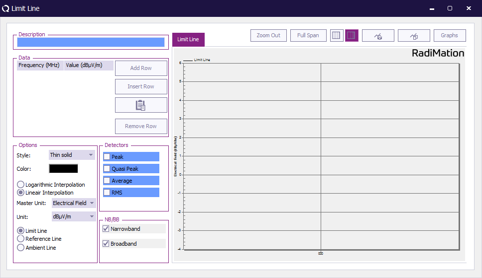
The default ''' 'Limit Line' window''' will appear. This window contains six fields; Description, Data, Options, Detectors, NB/BB and the graph area. | |||
[[Image:Limit Line Default.png]] | |||
==== Enter limit line information ==== | |||
To set up a limit line, enter the following information: | |||
{{ScreenElementDescriptionStart}} | |||
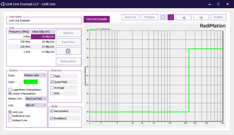
{{ScreenElementDescription|Description|Enter a file description for the limit line in the Description field (e.g. Limit Line Example).}} | |||
{{ScreenElementDescription|Data|Enter frequency-value pairs for the limit line in the Data field (see ‘Enter, edit & remove data pairs’ below).}} | |||
{{ScreenElementDescription|Options|Setup the Options field: | |||
* Select a line style and colour for the graph line. | |||
* Select either logarithmic or linear interpolation. In between the specified frequency points, the correct value of the limit line will be calculated by using either a logarithmic or linear interpolation over the frequency axis. This choice is depending on the requirements of the applicable standard. | |||
* Select the Master Unit (or Dimension) for the y-axis, (e.g. Electrical Field). | |||
* Select the Unit for the y-axis, (e.g. dBµV/m). | |||
* Mark the line as a Limit Line or Reference Line. The value of a limit line is compared to detected peaks. The value of a reference line is only usable as a graphical comparison with graphs.}} | |||
{{ScreenElementDescription|Detectors|Setup the Detectors field by selecting one or more detectors. During emission tests, {{RadiMation}} will check if the measured emissions are below the limit line(s). To perform this check in the correct way, the software must know for which detector(s) the limit line is valid.}} | |||
{{ScreenElementDescription|NB/BB|Setup the NB/BB field by selecting the option(s) Narrowband and/or Broadband.}} | |||
{{ScreenElementDescriptionEnd}} | |||
[[Image:Limitline file.png]] | |||
==== Enter, edit & remove data pairs==== | |||
* To enter a frequency-value pair, click the ''' 'Add Row' ''' or ''' 'Insert Row' ''' button, a new row will appear in the data field. Select the desired row and enter the frequency and value data, the limit line will be drawn directly in the graph. | |||
* To edit a data pair, select the desired value and/or unit of the data that you wish to edit and insert the new value and/or unit. | |||
* To remove a frequency-value pair, select the desired data pair and click ''' 'Remove Row' '''. | |||
=== Saving limit line files === | === Saving limit line files === | ||
Before a limit line can be saved, make sure the required information has been entered into the '''Description''', '''Data''' and '''Detectors''' fields. | |||
{{ | Otherwise a ''' 'RadiMation Warning' window''' will appear when you try to save the limit line. | ||
To save a Limit Line File, select ''' 'File' , 'Save Limit line' ''' (or ''' 'Save Limit line As…' '''). | |||
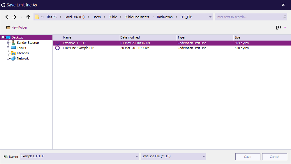
The ''' 'Save Limit line As' window''' will open. (The 'Limit Line' window will remain open in the background.) | |||
[[Image:File Save Limit Line.png]] | |||
{{RadiMation}} will ask you to specify and save a file name for the (new) Limit Line File. | |||
This can be the same or a different filename as used in the limit line '''Description''' field of the ''' 'Limit Line' window'''. | |||
Name the Limit Line File and click ''' 'Save' '''. (The 'Limit Line' window will remain open in the background.) | |||
[[Image:Save Limit line As.png]] | |||
=== Opening limit line files === | |||
To open an existing limit line file, select ''' 'File' , 'Open' , 'Limit Line' '''. The ''' 'Limit Line' window''' will open. | |||
[[Image:File Open Limit Line.png]] | |||
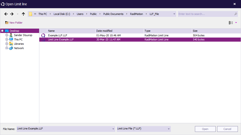
{{RadiMation}} will ask you to specify and open an existing Limit Line File. | |||
Select the desired Limit Line File and click ''' 'Open' '''. The specified ''' 'Limit Line' window''' will appear. | |||
[[Image:Open Limit Line.png]] | |||
== Correction files == | == Correction files == | ||
Correction files can be used to correct the frequency response of cables, generators, clamps, antenna’s, couplers etc. When the frequency response of a device is known, the operator can create a new correction file and assign it to the device. | Correction files can be used to for a lot of different purposes, for example to correct the frequency response of cables, generators, clamps, antenna’s, couplers, etc. When the frequency response of a device is known, the operator can create a new correction file and assign it to the device. From then on, every time that the device is used during a test, the values in selected correction are used to correct the measurement results. | ||
=== Creating correction files === | === Creating correction files === | ||
To create a correction file, | To create a Correction File, select ''' 'File' , 'New' , 'Correction' ''' or press ''' 'Ctrl+O' '''. | ||
{{ | |||
The window | [[Image:File new correction file.png]] | ||
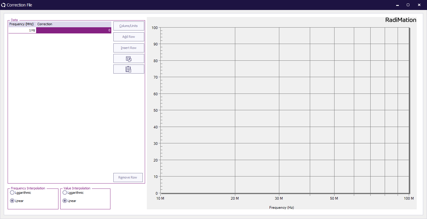
The default ''' 'Correction File' window''' will appear. | |||
This window contains three areas: Data, Options and the graph area. | |||
[[Image:New correction file.png]] | |||
==== Enter correction file information ==== | |||
To set up a correction file, enter the following information: | |||
{{ScreenElementDescriptionStart}} | |||
{{ScreenElementDescription|Data|Enter data pairs for the correction value in the Data field (see ‘Enter, edit & remove data pairs’ below).}} | |||
{{ScreenElementDescription|Options|Select either logarithmic or linear interpolation. | |||
In between the specified frequency points, the correct value of the correction value will be calculated by using either a logarithmic or linear interpolation over the frequency axis. This depends on the requirements of the applicable standard.}} | |||
{{ScreenElementDescriptionEnd}} | |||
==== Enter, edit & remove data pairs ==== | |||
The '''Data columns''' need to be defined before data pairs can be added. | |||
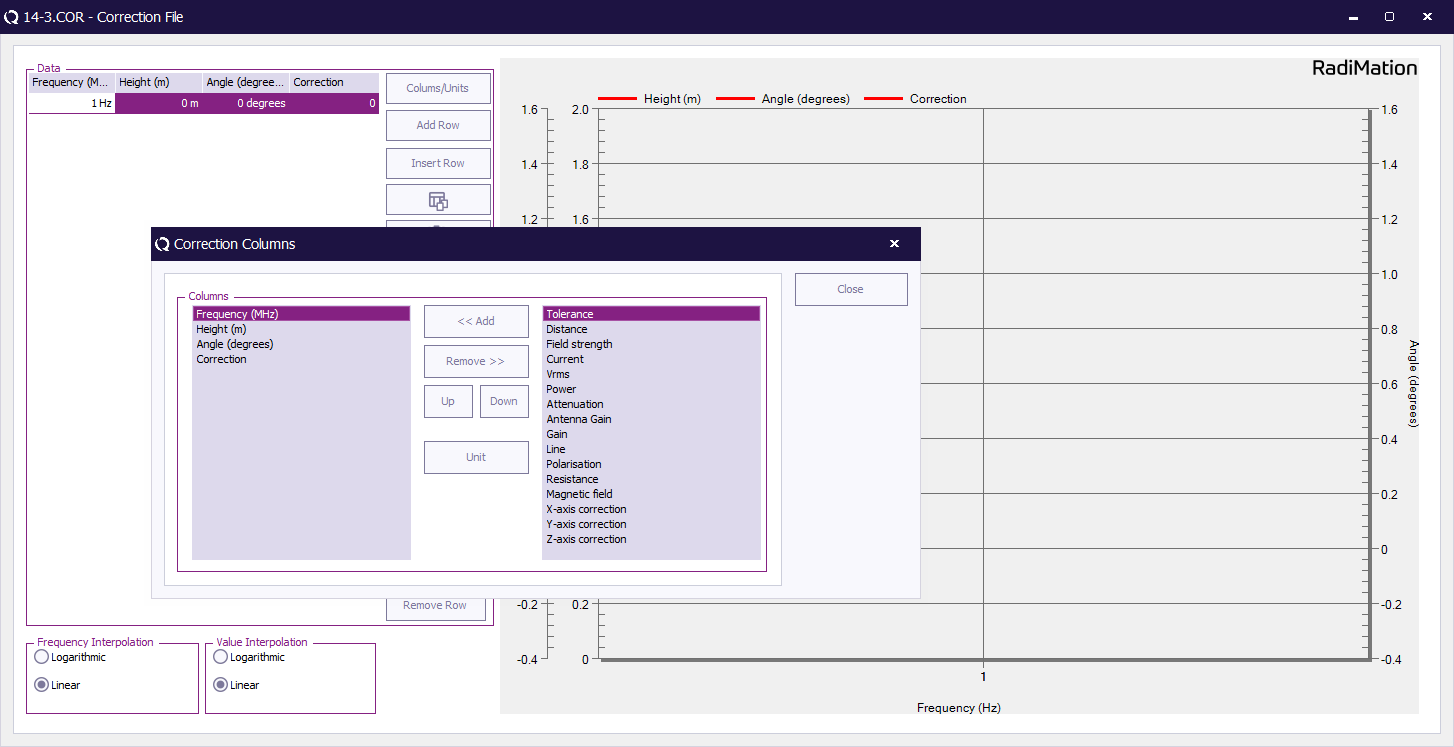
To select the desired columns (based on the use of the correction file), click ''' 'Columns/Units' '''. The ''' 'Correction Columns' selection window''' will appear where columns can be added and/or removed. Depending on the usage of the correction file, one or more columns can be selected. E.g. an amplifier limitation correction file will need two columns: frequency and power. A radiated emission test frequency list requires three columns: frequency, angle and height. A simple frequency list for an immunity test only contains a single column: frequency. Also the unit of each of the columns can be modified to represent the desired unit. | |||
Click ''' 'Close' ''' to return to the ''' 'Correction File' window'''. | |||
[[Image:Correction file correction columns.png]] | |||
* To enter a data pair, click the ''' 'Add Row' ''' or ''' 'Insert Row' ''' button, a new row will appear in the data field. Select the desired row and enter the information for the data pair, the correction value will be drawn directly in the graph. | |||
* To edit a data pair, select the desired value and/or unit of the data that you wish to edit and insert the new value and/or unit. | |||
* To remove a data pair, select the desired data point row and click ''' 'Remove Row' '''. | |||
==== Defining the units for the column ==== | |||
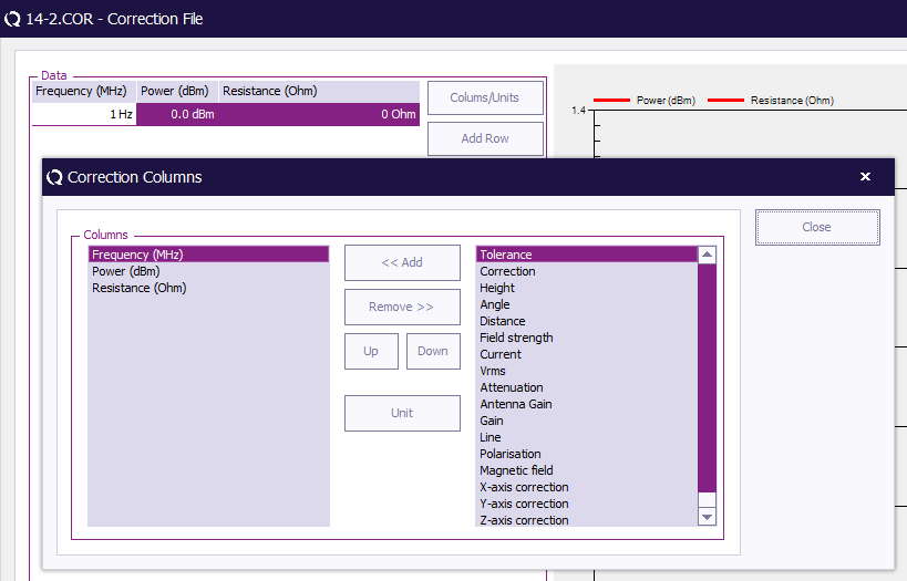
As shown in the paragraph above you can use the button ''' 'Columns/Units' ''' to add columns for specific types of information. | |||
[[Image:ColumnsCorrectionFile.png]] | |||
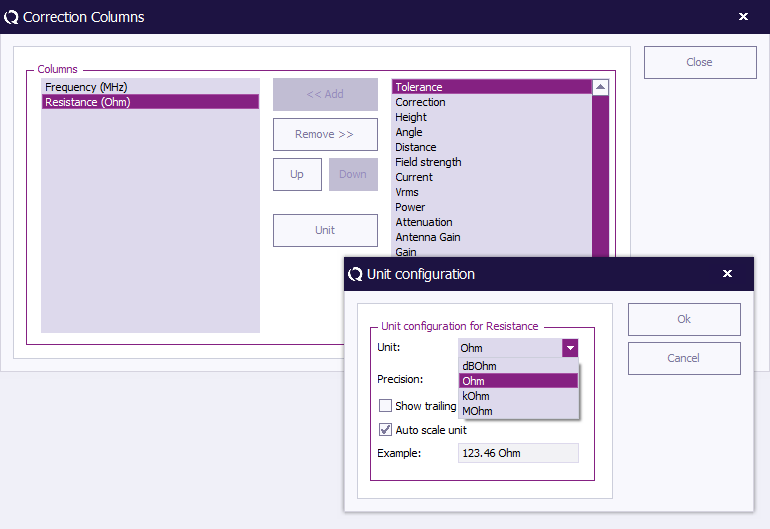
Correction files are being used in {{RadiMation}} to correct the data in a lot of different situations. An example of this would be when you add a new current sensor device to your setup, which should be corrected with the correct resistance. The correction factor you need to use is usually supplied by the manufacturer, but different manufacturers use different units to express the correction factor. To accommodate for this you can select a specific unit (like Ohm or dBOhm) for the resistance column. | |||
See the picture below on how to change the unit. | |||
[[Image:ChoosingUnitsForCorrectionColumn.png]] | |||
=== Saving correction files === | === Saving correction files === | ||
To save a Correction File, select ''' 'File' , 'Save Correction' (or 'Save Correction As…'). | |||
(The 'Save Correction As' window will open. The 'Correction File' window will remain open in the background.) | |||
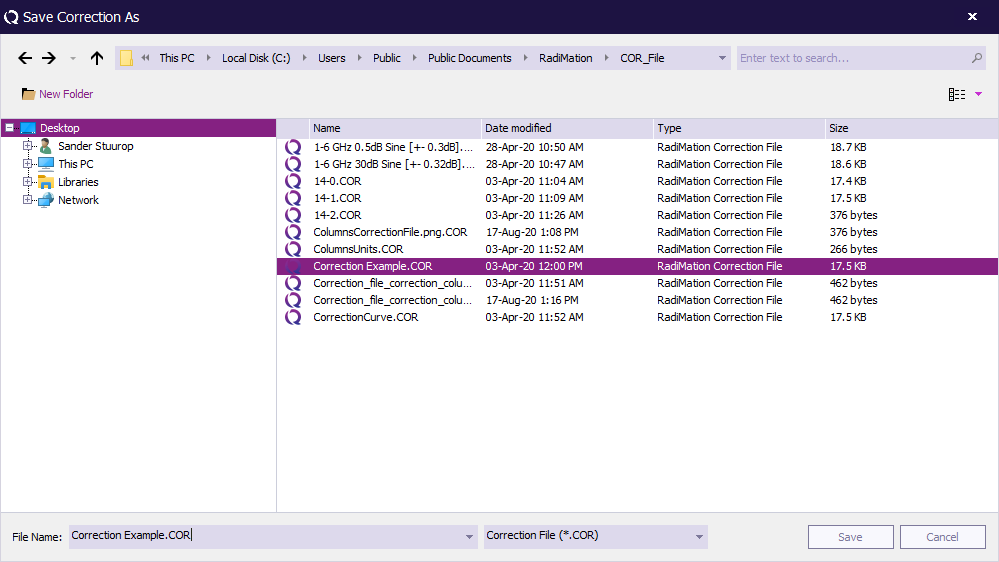
[[Image:File save correction.png]] | |||
{{RadiMation}} will ask you to specify and save a file name for the (new) Correction File. | |||
Name the Correction File and click ''' 'Save' '''. (The 'Correction File' window will remain open in the background.) | |||
[[Image:Save correction as.png]] | |||
=== Opening correction files === | |||
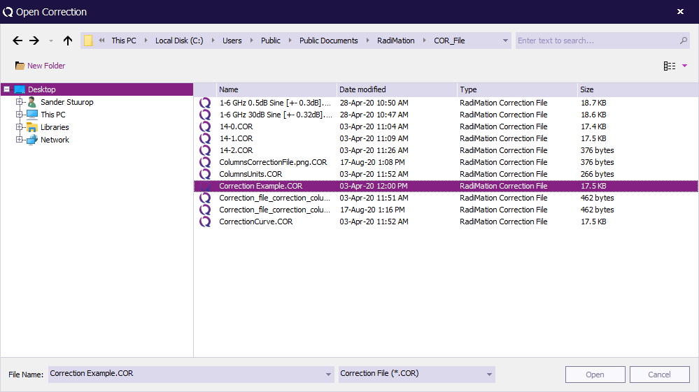
To open an existing limit line file, select ''' 'File' , 'Open', 'Correction' '''. (The 'Open Correction' window will open.) | |||
[[Image:File open correction.png]] | |||
{{RadiMation}} will ask you to specify and open an existing Correction File. | |||
Select the desired Correction File and click ''' 'Open' '''. (The specified 'Correction File' window will appear.) | |||
[[Image:Open correction.png]] | |||
== Using Test Setup Files (TSF) == | |||
{{RadiMation}} is a modular integrated test software package, which, in its full configuration, can perform full automatic EMC tests. The software package includes [[Radiated immunity]] tests [R.I.], [[Conducted immunity]] tests [C.I.], [[Radiated emission]] tests [R.E.] and [[Conducted emission]] tests [C.E.]. (For more information about the modular test package, consult the [[#Software overview|software overview]].) | |||
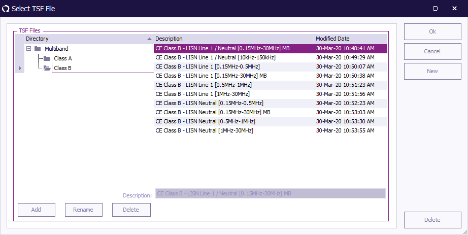
The test configuration data for each type of test (such as start/stop frequency, test level, dwell time, etc.) can be saved in a Test Setup File (*.TSF). This file also stores the calibration file and test site information. Save the TSF file with a clear name/description for future reference. A maximum of 40 characters can be used for the description of the TSF file. When the same type of test must be performed, one can simply load the matching TSF file and start the test. | |||
{{RadiMation}} enables the user to create a directory tree to organize and store the different TSF files in a structured way. | |||
[[Image:Select TSF File.png]] | |||
A more advanced use of the TSF files takes place during sequence testing. In a sequence, different TSF files (even from different types of tests) can be lined up and started without the intervention of a test engineer. | |||
(See [[Chapter 11|Chapter 11 "Sequence Testing"]] for more information.) | |||
== Viewing test data == | == Viewing test data == | ||
{{RadiMation}} stores all the test data in the corresponding EUT files. To view the test data, open the desired EUT file. (Select 'File , 'Open' , 'EUT' to do so.) | |||
[[Image:File open eut.png]] | |||
The ''' 'EUT' window''' will show a list of all the performed tests for the selected EUT (in the 'Main' tab). | |||
To view the extended data from a single test, select the desired test from the list and click the ''' 'Info' button ''' on the right side of the window. | |||
[[Image:EUT main info.png]] | |||
A ''' 'test data window' ''' will open, displaying all the data for that test. This includes general information, such as: | |||
* Time and date of the test | |||
* Equipment used during the test (including serial numbers) | |||
* Test engineer | |||
* Notes | |||
* Ambient information | |||
And test specific information, such as: | |||
* Test graphs | |||
* Test configuration data | |||
* Calibration file used during the test (if applicable) | |||
[[Image:EUT test data example.png]] | |||
== Printing test data == | == Printing test data == | ||
Test data can be printed in a few different ways. | |||
Open the ''' 'EUT' window''' ('File' , 'Open' , 'EUT') that contains the desired test data and select the most appropriate print option for your situation: | |||
# To print part of the data from one test; | |||
#* Select the desired test (in the 'EUT' window) and click ''' 'Info' ''' at the right side of the list. | |||
#* Select the graph that you want to print (in the 'test data window'). The graph will be displayed on the screen. | |||
#* Click the ''' 'print graph' button ''' above the graph (containing a graph and printer icon). The selected graph will be printed. | |||
# To print all the data from one test; | |||
#* Select the desired test (in the 'EUT' window) and click ''' 'Print' ''' at the right side of the list. The data from the selected test will be printed. | |||
# To print the data of more than one test; | |||
#* Select the desired tests (in the 'EUT' window) while holding the ''' 'Shift' ''' button. | |||
#* Click ''' 'Print' ''' at the right side of the list, the selected tests will be printed. | |||
{{Warning|Printing from {{RadiMation}} will be done by your default Windows printer (with its default settings). To change the printer/settings used by {{RadiMation}}, please change the default printer settings in your Windows environment.}} | |||
== Report generation == | |||
{{RadiMation}} can use the information of the performed tests to automatically generate a report as well as export all the data to Microsoft Excel. | |||
This can be done with the [[Report Generator]] and [[Excel Exporter]]. Please read [[Chapter 13]] for detailed descriptions of these functions. | |||
== Ambient information == | |||
During EMC tests, ambient temperature, air pressure and relative humidity can influence test accuracy. Because of this most EMC standards define (at the very least) the temperature range in which EMC tests must be performed. | |||
Each test configuration menu allows you to enter a value for the temperature, pressure and relative humidity at the start of the test. This data can be entered, and viewed, in the ''' 'Environmental Data' window''', which can be opened from any ''' 'test data window' '''. | |||
To open the ''' 'Environmental Data' window''', click the ''' 'Environment' button''' in the ''' 'test data window' '''. | |||
== | [[Image:EUT new test environmental data.png]] | ||
== The first test == | |||
Now that we successfully have installed RadiMation and know how to configure the general settings we can launch RadiMation with a (default or created) test engineer account. | |||
Most importantly, we are able to create and configure the device drivers needed for our test setup and add them to our created test equipment. | |||
Also, when we need Correction files and/or Limit Line Files we know how to handle them. | |||
Creating or opening an EUT file and the general EUT overview has been explained. | |||
To start performing tests it is necessary to have an EUT opened and to create your first TSF (Test Setup File). | |||
Proceed to the next Chapters of the manual to read on how a test is configured. For some tests it is required to run a calibration first in order to run. | |||
[[Category:Manual]] | |||
Latest revision as of 18:50, 6 October 2024
Getting started[edit]
Chapter 2 “Getting Started” provides information relevant to first time use of RadiMation®. This includes (but is not limited to) a product overview and installation guide, as well as the configuration of some basic settings (such as passwords, users, languages and test parameters).
For more (detailed) information, follow the links and references in the text, or go straight to the chapter related to your topic of interest.
Software overview[edit]
RadiMation® consists of a software core and 7 complementing software modules. It can be used to perform 5 different types of EMC tests, calibrations, sequence testing and has an automatic report generation function.
An overview of the RadiMation® software is visible in the figure below:
The RadiMation® Core consists of the following components:
- The Visual and Graph System
- The EUT data management System
- Sequence Testing
- Calibration
- Data Logging
- Database Functionality
- The Device Driver System
Depending on the requirement, one ore more modules can be added to the RadiMation® Core.
The different modules are integrated in one single software package. The separate modules are:
- Radiated immunity testing (RI)
- Conducted immunity testing (CI)
- Pulsed immunity (ESD, EFT, Surge)
- Radiated emission testing (RE)
- Conducted emission testing (CE)
- Report generator
- Excel Exporter
The implementation of different modules in one software package has a number of advantages compared to other software:
- Easy to use because all the modules have the same "look & feel".
- Seamless data exchange between the different modules.
- Calibration functionality enables an easy exchange of the calibration files.
- Different types of tests can be performed, fully automatic, after each other (Sequence testing).
- Fast automatic report generation, made possible by one data repository for all test data.
Conventions[edit]
RadiMation® uses the Windows structure of pull down menu’s. In this manual the pull down menu’s are visualized as followed:
-
 File
File
-
 Open
Open
-
 EUT
EUT
-
-
-
The example above shows that, to show the file open selection window, the 'File' item from the menu bar should be selected first, followed by the 'Open' item and then the 'EUT' item.
A screenshot of these menu items is visible below:
Hardware and software requirements[edit]
There are certain requirements that the PC(-environment, used to perform the EMC tests) needs to comply with to run RadiMation®.
Hardware requirements[edit]
The RadiMation® software makes extensive use of data calculations, bus interactions (to control the test equipment) and screen interactions (for the use of graphs). Because of this the processor performance is very important and a dedicated PC for RadiMation® is required. Running other programs on the same computer can cause compatibility problems and is not supported. Programs which are supported are the programs used by RadiMation®, such as Word, Excel and MySQL.
To use the software to its full extent the following hardware configuration is required:
- Processor architecture: x64 (ARM64 is not supported)
- Processor clock speed: 2 GHz minimum, > 3 GHz recommended
- Free RAM memory: 2 GB minimal, > 4 GB recommended
- Free hard disk space: 1 GB minimal
- Monitor resolution: Full HD (1920 x 1080) or larger
- IEEE card: Any GPIB Card that is supported by the National Instruments NI-488.2 Software Library
Memory[edit]
RadiMation® needs a considerable amount of memory to perform at its best. We recommend that you have at least 512 MB (Mega Bytes) of free memory available, but more if possible. Free memory is defined as the amount of free RAM without having to use the swap file. Thus, not the specification of the total amount of memory that the machine has. The following steps are to help you determine the amount of free memory in your PC:
- Cold boot your machine from power off, not from hibernate or restart.
- Determine the total amount of memory put into the computer.
- Start the windows task manager and determine the commit charge.
- Calculate the amount of free memory by subtracting the amount of memory of the commit charge from the amount of memory put in the computer.
If the amount of free memory is less then 512 MB, there are several options to obtain more free memory. Depending on the configuration and situation, the following options are available:
- Insert additional memory modules into the machine.
- Remove/uninstall programs with large memory usage that do not involve measuring, for example VNC viewers.
- Prevent programs from starting automatically during the booting of the computer.
GPIB card[edit]
If a GPIB connection to one of the measurement equipments is used, the GPIB hardware and software needs to be installed correctly before RadiMation® is installed. Raditeq is not responsible for any additional costs or delays that may occur if this card is not installed prior to the installation of RadiMation®. The used GPIB card has to be supported by the National Instruments NI-488.2 software library. At least version 15.0 or higher of the NI-488.2 software should be used. RadiMation® is able to use any version of National Instruments NI-488.2 which is 15.0 or higher, so it is not needed to update the NI-488.2 library as long as the installed version is supported by National Instruments and RadiMation®.
Software requirements[edit]
The RadiMation® software is supported on all the Microsoft Windows, Windows Enterprise and Windows Server 2019 (or higher) operating systems that are still supported by Microsoft. The IoT variant of these operating systems are not supported. If a specific version of Microsoft Windows is still supported, can be checked on Microsoft Lifecycle Policy pages. Both the 32-bit and 64-bit versions of these operating systems are supported. In order to run RadiMation it is required that the used operating system is up to date. It can result in severe delays during an installation in the case that Windows Updates are not completely updated and installed.
Microsoft .NET framework[edit]
The Microsoft .NET Framework 4.8 is also required, on Windows 10 1903 and higher this is installed by default. For Windows 10 October 2018 Update (Version 1809) the .NET framework 4.8 needs to be installed manually before installing RadiMation®
Microsoft office[edit]
It is required to have a supported, licensed and working version of Microsoft Office Word installed on the PC. This should be at least Microsoft Word 2016 or higher, as Microsoft Word 2013 and lower has no mainstream support anymore from Microsoft. RadiMation® uses Microsoft Office Word to generate and print the printouts, besides creating the reports. The RadiMation® report generater can create reports in the following formats:
Installation[edit]
During the installation of RadiMation® a network/PC administrator from the IT department must be available. This person must be able to grant rights (for one day or more) and have sufficient knowledge of the (local) network. Raditeq is not responsible for any additional costs or delays that may occurs if this support is not provided.
When RadiMation® is installed for the first time, it needs to be installed with administrator rights. Upgrades have no need for full rights (although rights to perform installations are required). To update RadiMation® the following rights needs to be set:
- Read rights to the 'C:\' drive
- Full rights to the installation directory (e.g. 'C:\Program Files\Raditeq', please note that the path may be different depending on the used OS and language)
Software installation[edit]
First time software installation[edit]
To install the RadiMation® software, please download the RadiMation® setup program from our download website at: https://www.raditeq.com/radimation-download/ . Once the download has been finished, the setup program can be started. The Installation Wizard will guide you through the installation process. After installation the computer must be restarted before running RadiMation®. Please read User rights and installation about the user rights and information that is required for first time installation.
Software installation on a network[edit]
In a network environment multiple computers are connected with each other though a shared communication medium. This provides several advantages compared to a local installation. One of these benefits is that data can be shared between the connected computers. The RadiMation® software is designed to optimally use this advantage. All the data that is used or generated by RadiMation® can also be shared on the network. In most cases we recommend the use a of network configuration over a local configuration.
| Note: | When RadiMation® is using a network configuration the program itself will still be executed from the local computer. It is therefore neither cached nor running directly from the network. |
To fully use the functionality of data sharing, the configuration of RadiMation® should be changed slightly. Make the necessary alterations by following the steps below:
- Create a shared network directory (with the appropriate rights) on one of the Network Servers. Your Network Administrator can help you with this. This directory will be called <NetworkDir> from now on.
- Create a drive assignment for this specific <NetworkDir>. This will avoid the use of excessive path depths. Your Network Administrator can also help you with this step.
- Create a sub-directory with the name <Setup> in the <NetworkDir>.
- Copy the RadiMation® setup.exe file from the CD-ROM (or, if you downloaded RadiMation®, directly from local disk) to the <Setup> directory in the <NetworkDir>.
- Install RadiMation® on one of the network computers. This can be done by launching the setup.exe program. Use the installation procedure as described in the previous section.
- In the <NetworkDir>, create the following sub-directories:
- CAL_File
- CONFDVDR
- COR_File
- EUT_File
- LLF_File
- Printout
- RGO_File
- RGT_File
- SEQ_File
- TSF_File
- Start the installed RadiMation® program and open the Configuration window. On the Directories tab, change the location of the Device Driver Configuration directory to the CONFDVDR directory in the <NetworkDir>. (Note: do not change the other directories yet.)
- Restart the RadiMation® program.
- Open the Configuration window again and on the Directories tab, change the location of all the other directories to the corresponding directories in the <NetworkDir>.
- Restart the RadiMation® program again.
- The RadiMation® program will use the <NetworkDir> as its main data directory from now on.
- Start the Configuration of the RadiMation® software as described in the remaining part of this chapter. The complete configuration will be written to the <NetworkDir>.
When the RadiMation® software is installed on another computer in the network, the following steps can be used:
- Install the RadiMation® software from the <Setup> sub-directory in the <NetworkDir>. Use the installation procedure as described in the previous section.
- Start the installed RadiMation® program and open the Configuration window. On the Directories tab, change the location of the Device Driver Configuration directory to the CONFDVDR directory in the <NetworkDir>.
- Restart the RadiMation® program.
The newly installed RadiMation® will now use the already configured <NetworkDir>.
Automated / Silent installation[edit]
RadiMation® is not provided as a .MSI file that can be used by network administrators to perform an automated installation on a lot of PC's. However RadiMation® is provided as an .EXE file that does accept additional command line arguments that can be used to perform an automated silent installation. The following arguments can be specified to the RadiMation® setup .EXE program:
| Argument | Purpose and explanation |
|---|---|
| /SP- | Disables the 'This will install ... Do you wish to continue?' prompt at the beginning of the setup |
| /SILENT | Instructs the setup program to be silent |
| /VERYSILENT | Instructs the setup program to be very silent |
| /SUPPRESSMSGBOXES | Instructs the setup to suppress message boxes |
| /LOG | Causes setup to create a log file in the user's TEMP directory |
| /LOG="filename" | Same as /LOG, except it allows to specify a fixed path/filename to use for the log file. |
| /NOCANCEL | Prevents the user from cancelling during the installation process. |
| /NORESTART | Prevents Setup from restarting the system following a successful installation, or after a Preparing to Install failure that requests a restart. |
| /DIR="x:\dirname" | Overrides the default directory name |
| /HELP | Shows a detailed explanation of all the command line parameters |
The RadiMation® SETUP.EXE also contains the DRIVERS.EXE that was actual at the moment that the SETUP.EXE was build. That embedded DRIVERS.EXE will automatically be installed during the installation of the RadiMation® version. If in the same directory in which the SETUP.EXE is located, also an 'AUTOINSTALLDRIVERS.EXE' is present, then that 'AUTOINSTALLDRIVERS.EXE' will be installed instead of the embedded DRIVERS.EXE. The 'AUTOINSTALLDRIVERS.EXE' can be created by just renaming the desired DRIVERS.EXE to 'AUTOINSTALLDRIVERS.EXE'.
Installing software updates[edit]
Software updates can be downloaded from the RadiMation® Download page. These updates are supplied as RadiMation® versions with a higher version number.
Once the download of the new version has been finished, the setup program can be started. The setup program will install the new RadiMation® version at the same location as the previous older, but in a separate installation folder. This will allow you to use the previously installed RadiMation® version, as well as the new one.
Installing from a network directory[edit]
If the already installed RadiMation® version was installed from a network directory, the new setup file can be copied to the <Setup> sub-directory of the <NetworkDir>.
The new RadiMation® version can then be installed on each computer from that <Setup> sub-directory. This installation still has to be started manually, RadiMation® will not automatically detect that a newer version is available on the network directory, and it will not automatically start the installation of the newer version.
Updating device drivers[edit]
After the new RadiMation® version is installed, we strongly recommend that you install the latest device drivers as well. These device drivers can be installed by starting the ‘DRIVERS.EXE’ program that can be downloaded from our RadiWiki website.
The DRIVERS.EXE program will detect the different RadiMation® versions installed on your PC. A dialog will start, asking you to select the RadiMation® version that needs updated device drivers. Select the latest version of RadiMation® that was just installed.
You have successfully obtained the latest released version of RadiMation® when both the software and device drivers have been updated.
| Note: | We strongly advice that a you make a complete backup of all your files and directories (e.g. TSF/Sequence/Correction/Calibration and EUT) before installing a RadiMation® update. |
| Warning: | Do NOT uninstall RadiMation®!! This will cause removal of all user settings, TSF, sequence, calibration and correction files. This is unrecoverable. |
User rights and installation[edit]
For a new installation or an update, different user rights can be setup.
New installation[edit]
A new installation can only be performed with administrator rights. When installed without administrator rights a successful installation is not guaranteed.
Update[edit]
To update the RadiMation® software, the user must have the rights to read and write in the RadiMation® folder, which is normally located in the C:\Program Files (x86)\Raditeq\ directory.
Daily usage[edit]
For daily usage of the RadiMation® software, no specific rights are needed. Every standard end-user should be able to start and use the already installed RadiMation® software.
Software protection key[edit]
The RadiMation® software is copy protected with an USB Software protection key. The USB Software protection key should be connected to the PC while a RadiMation® test is running, or when the report generator or Excel Exporter is used. The USB Software protection key is not needed to open and review the test results.
A network license or a floating license of the USB Software protection key is not available, and each RadiMation® test PC should thus have it's own USB Software protection key physically connected to the PC.
Software configuration[edit]
In the main menu, under the configuration pull down menu, a number of standard configurations can be made. The selected and/or entered configurations will be used as the default settings for future use.
The next paragraphs will explain the required configurations.
Password protection[edit]
RadiMation® allows to protect a number of configurations by assigning applicable rights to an engineer, where also a login password can be configured for those engineers.
- The password protection is by default turned on for the default engineer with the name: 'Administrator'.
- The default password is Radimation.
- Configuring and using additional engineers with different passwords is optional.
- The configured engineers are stored in the Device Driver Configuration Files directory, which can be configured using the menu:
-
 Configuration
-
 Configuration
-
 Directories
-
-
-
To change the password protection settings, go to the Engineers window in the Configuration tab.
Select the Administrator engineer and click Edit.
In the Test Engineer window for the 'Administrator' user, the password can be enabled, disabled or modified.
The current password setting for the selected engineer is displayed at the bottom of the window. This will indicate whether a password has been ‘set’ or ‘not set’.
In addition, the protection can be enabled or disabled for the following items:
| Prevents unauthorized changes to test equipment configuration. |
| Prevents unauthorized changes to test engineers configuration. |
| Prevents unauthorized changes to Test Setup Files (TSF) files. |
| Prevents unauthorized changes to Limit Line Files (LLF) files. |
| Prevents unauthorized changes to correction files. |
| Prevents unauthorized changes to the general configuration. |
To enable, disable or change the password, click Change Password.
To change the password, enter the old password and the new password (twice), then click OK. You will be returned to the Test Engineer window.
To disable the password, enter the old password and leave the other two fields empty, then click OK. You will be returned to the Test Engineer window.
(The password indication will change to: "Warning: Password is not set for this engineer.")
To enable the password, enter the new password (twice), then click OK. You will be returned to the Test Engineer window.
(The password indication will change to: "Password is set for this engineer.")
To leave the Engineers window, click Ok.
Test engineers[edit]
For each test, the name of the test engineer performing the current test can be entered.
To add, delete or edit (the names of) test engineers, go to the 'Engineers' window in the 'Configuration' tab.
The Engineers window will show the current configured list of engineers. To leave the 'Engineers' window, click 'OK' .
To add a new test engineer, click 'Add' .
Enter the name and set the rights of the new engineer, then click 'OK' . You will be returned to the 'Engineers' window.
The new engineer will not have a protection password (yet), this can be enabled by clicking 'Change Password' . Please read Password protection for more information.
To delete a test engineer, select the engineer and click 'Delete' .
To confirm that you want to delete the engineer from the configuration list, click 'Yes' .
If you do not want to delete this engineer from the list, click 'No' or 'Cancel' . You will be returned to the 'Engineers' window.
To edit the name, rights and/or password of an engineer, select the engineer and click 'Edit' .
Make the desired changes in the 'Test Engineer' window and click 'OK' .
If you want to undo or cancel your changes, click 'Cancel' . You will be returned to the 'Engineers' window.
Default address information configuration[edit]
When a new EUT file is created, the name and address information of the manufacturer, test house and client can be entered separately.
In many situations one or more of this information will be the same for different EUT files (i.e.: when a test house owns the software, the test house data will always be the same).
To prevent users from having to enter repetitive data input, RadiMation® provides the option to set default address information for:
- The default client
- The default manufacturer
- The default test site
The default address information is stored in the Device Driver Configuration Files directory, which can be configured using the menu:
-
 Configuration
-
 Configuration
-
 Directories
-
-
-
Data entered under Default Address Information, will automatically be copied and stored in the EUT file. Specifying this information is not required, however it has the benefit that address information that is always the same doesn't need to be entered over and over again in every new EUT file. To add, modify or delete the default address information, go to the Default Address Information window in the Configuration tab.
Enter the desired information as shown in the example below.
To confirm the data input, click OK, to cancel the data input, click Cancel. The Default Address Information window will close.
Default Units[edit]
RadiMation® allows the user to define the default units. These units are used throughout the software package and can be changed at any time during measurements and viewing.
To configure the unit settings, go to the 'Configuration' window in the 'Configuration' tab.
The default settings for the different units can be set in the 'Units' tab.
It is possible to define different units for different tests. The following can be selected:
- Radiated Immunity
- Conducted Immunity
- Radiated Emission
- Conducted Emission
- Pulsed Immunity
- Antenna Diagram
- RadiCal
To change the settings of a unit, choose the desired test (e.g. Radiated Immunity) from the drop down menu in the 'Units' tab.
Select the measurement (e.g. Power) and click 'Change'.
The 'Unit configuration' window will appear, allowing you to change the parameters of the unit.
To confirm your changes, click 'OK' , to cancel your changes, click 'Cancel' . You will be returned to the 'Configuration' window.
Click 'Close' to leave the 'Configuration' window.
Default directories configuration[edit]
The RadiMation® software can use different directories to store different data file types.
The location of the following file types can be specified:
- Equipment Under Test Data files (*.EUT files),
- Correction files (*.COR files)
- Calibration files (*.CAL files),
- Configuration files (*.TSF files),
- Sequence files (*.SEQ files),
- Limit line files (*.LLF files).
- Printout files (*.DOC files).
The different file types are described in Chapter 18 “RadiMation® file types and locations”.
For each data type the default location can be entered through the configuration. The path name can link to a directory on a local or network drive.
Selecting a network drive will allow you to store data (e.g. EUT data) on a computer network, making it more accessible.
To modify a path name, go to the 'Configuration' window in the 'Configuration' tab.
Go to the 'Directories' tab, select the directory that you wish to change and click 'Change' .
The 'Browse For Folder' window will appear, allowing you to select (or make) a new folder in your directory.
To confirm your change, click 'OK' , to cancel your change, click 'Cancel' . You will be returned to the 'Configuration' window.
Click 'Close' to leave the 'Configuration' window.
Device driver configuration[edit]
Device drivers let your software know which equipment has to be used and controlled during EMC tests.
In RadiMation®, the device drivers only need to be configured to the customer requirements once.
During the configuration of the device driver, information such as the IEEE address or RS232 COM-port has to be entered.
You can configure the device drivers in the 'Configuration' window.
This window can be accessed in one of two ways, either through the 'Configuration' tab or through the 'Devices' tab.
To configure a device driver, go to the 'Device Drivers' tab in the 'Configuration' window.
Select the desired 'Device Driver Type' from the drop-down menu (e.g. Signal Generator). The available drivers for that type will be shown.
To create a new RadiMation® device driver, select the desired 'Device Driver Type' (e.g. Signal Generator) and click 'Add' .
Select a new device driver (in the scroll menu or through the search function) and click 'New' .
To cancel your selection and return to the 'Configuration' window, click 'Close' .
The name/description of the chosen device driver can be changed in the 'Device Driver Configuration' window.
To confirm your changes (or the provided description), click 'OK' , the 'Device Driver Settings' window will appear.
To cancel your changes, click 'Cancel' . You will be returned to the previous window (e.g. New Signal generators).
The 'Device Driver Settings' window will appear with information on the selected device driver. In this window information can be added, edited and removed.
To confirm the settings, click 'OK' , to cancel your changes, click 'Cancel' . You will be returned to the 'Configuration' window.
More detailed device driver settings are described in the paragraph "Device Driver settings" in Chapter 14.
To edit an existing device driver, select the desired (device driver) type and device driver, then click 'Edit' . (The 'Device Driver Settings' window will appear.)
To remove an existing device driver, select the desired (device driver) type and device driver, then click 'Remove' .
A confirmation window will appear. To remove the selected device driver, click 'Yes' , to cancel, click 'No' . You will be returned to the 'Configuration' window.
Click 'Close' to leave the 'Configuration' window.
Graphics configuration[edit]
RadiMation® allows you to customize the way graphics are displayed on your screen.
To configure the style of the shown graphs, go to the 'Configuration' window in the 'Configuration' tab.
An example graph is shown in the 'Graphs' tab that is created with the current settings. To change these graph settings, click 'Customize' .
The 'Graph Customization Configuration' window contains three tabs; 'Chart' , 'Graph' and 'Markings' .
The 'Chart' tab contains the settings related to the overall graph and can be used to determine the colours, layout and titles.
The 'Graph' tab contains the settings related to the graph lines shown in the graph and can be used to determine the colours, scaling and layout of each and every shown graph line.
The 'Markers' tab contains the settings related to the markers on the graph and can be used to determine the colours, style and scaling of each and every shown marker.
To change the graph settings, select a graph (component) in the left section of the window, then make the desired changes in the right section of the window.
Click 'Update' to update the graph settings without closing the 'Graph Customization Configuration' window. This will allow you to see the effect of the new settings and make additional changes.
Click 'Close' to update (and save) the graph settings and close the 'Graph Customization Configuration' window. You will be returned to the 'Configuration' window.
The selected settings in the 'Graph Customization Configuration' window are used as the RadiMation® default settings. It is still possible to overrule these settings for individual tests to more specific settings.
Click 'Restore factory default' to return to the factory settings.
Database Configuration[edit]
Introduction[edit]
RadiMation® can retrieve customer information (such as name and address) from external databases, for example from your company's customer relationship management (CRM) database. This option is called Customer database and will reduce the need to manually enter large amounts of customer information in RadiMation®.
Customer database can interface with several external databases, such as:
Changing the customer database driver[edit]
To configure RadiMation® to support your customer database, go to the 'Configuration' window in the 'Configuration' tab.
Go to the 'Database' tab to select and/or change the Customer Database and Device Driver Databases.
To select a Customer Database, select a database type from the pull-down menu.
To see and/or change more detailed settings (of the selected database type), click 'Configuration' .
The 'Customer database configuration' window will appear. (This window can differ depending on the selected database type).
To confirm your changes, click 'OK' , to cancel your changes, click 'Cancel' . You will be returned to the 'Configuration' window.
For more detailed information on the Database Configuration settings, go to Chapter 14 “Database Configuration”. Information on the settings of the different database types can be found in the paragraphs that follow “Database Configuration”.
To select a Device Driver Database, select a database type from the pull-down menu.
To see and/or change more detailed settings (of the selected database type), click 'Configuration' . A dedicated window will appear. (This window can differ depending on the selected database type).
To confirm your changes, click 'OK' , to cancel your changes, click 'Cancel' . You will be returned to the 'Configuration' window.
Click 'Close' to leave the 'Configuration' window.
Language Selection[edit]
RadiMation® supports multi-language use. This means that the software package can be operated in several language.
In addition, the multi- language support allows for easy translation from English to most other languages.
Please contact your local reseller for the availability of your required language driver.
The default language of RadiMation® is English.
To change the language settings, go to the 'Configuration' window in the 'Configuration' tab.
Go to the 'Language' tab. The current language setting is marked with the text (current).
To change the language setting, select one of the other languages, click 'Close' (to leave the 'Configuration' window) and restart RadiMation®.
The selected language will only be active after RadiMation® is restarted.
| Note: | Not all languages are currently available. Please contact your local reseller for language availability. |
Product Standard[edit]
Introduction[edit]
Product Standards describe the requirements (e.g. dimensional, technical, etc.) and the methods of testing (as well as grading, marking, etc.) of a product.
The objective of these standards is to define and impose 'standards' that will ensure that the product in question will not represent harm or hazard to consumers.
Because the standards with regards to product testing can be relevant to RadiMation® users, RadiMation® offers the possibility to add this documentation to your configuration.
There are many Product Standards for individual products and product types. These, in turn, often refer to multiple Basic Standards.
Where a Product Standard describes all the tests that should be performed on a EUT, a Basic Standard only describes one single test.
For example:
The Product Standard for product X describes four different requirements/tests that the product needs to comply with.
These four tests are described in four Basic Standards, where each basic standard describes the requirements for one test.
Basic Standards can also be added to RadiMation®.
In addition, one single Technical Setup File (TSF) can be generated for each Basic Standard, configured to perform the test as described in the standard.
Adding a Product Standard[edit]
To add a Product Standard to RadiMation®, go to the 'Configuration' window in the 'Configuration' tab.
Select the 'Product standards' tab and click 'Add' .
(To edit a Product Standard, select the standard and click 'Edit' . To remove a Product Standard, select the standard and click 'Remove' .)
Insert the required information in the 'Standard details' window (as visible in the example below).
Please note that the Official name can only be inserted the first time and has to be unique.
In addition, it is possible to link a file to the standard in the File location field. For example a PDF, DOC or HTML file that describes the standard.
RadiMation® will open the file (with the default reader for this file type) when the engineer selects the magnifying glass button next to that field.
To confirm your data input, click 'OK' , to cancel your input, click 'Cancel' . You will be returned to the 'Configuration' window.
Add(ing) Basic Standard(s)[edit]
To add a Basic Standard to the product standard, click 'Add' . The 'Select Standard' window will appear.
Select one or more Basic Standards (hold the ‘Ctrl’ key to select multiple standards) and click 'Select' .
To cancel your selection, click 'Cancel' . You will be returned to the 'Standard details' window.
To see the details of a Basic Standard, double click the standard or click ‘Details’.
| Note: | When a product standard is selected or added in the 'EUT' window, the data of that standard is copied into the EUT Document. At that moment a copy of the data of the standard from the configuration is made. This means that, if the configuration of a standard in the 'Configuration' window of RadiMation® is changed, the data in the EUT file will still have the old data of the standard!!! This is as it should be, because this is the information of the standard that is used at the time that the EUT was tested. |
Basic Standard[edit]
To add a Basic Standard to RadiMation®, go to the 'Configuration' window in the 'Configuration' tab.
Select the 'Basic standards' tab and click 'Add' .
(To edit a Basic Standard, select the standard and click 'Edit' . To remove a Basic Standard, select the standard and click 'Remove' .
Please note that removing a Basic Standard from the list will also remove any references of this standard entered in the Product Standards.)
Insert the required information in the 'Standard details' window (as visible in the example below).
Please note that the Official name can only be inserted the first time and has to be unique.
In addition, it is possible to link a file to the standard in the File location field. For example a PDF, DOC or HTML file that describes the standard.
RadiMation® will open the file (with the default reader for this file type) when the engineer selects the magnifying glass button next to that field.
To confirm your data input, click 'OK' , to cancel your input, click 'Cancel' . You will be returned to the 'Configuration' window.
Test equipment list configuration[edit]
The test equipment configuration contains a list of all the test equipment used during a test. The software uses this list to determine which device drivers should be used to control the test equipment. RadiMation® allows you to configure specific test equipment lists for each type of test as well as different test equipment lists for the same type of tests. (This can be useful if you have, for example, more than one signal generator to perform conducted immunity tests with).
In the 'Test Equipment' window a set of test equipment will be selected. When a calibration file is generated, RadiMation® will record this test equipment configuration together with the calibration data. When a substitution test is started, the test equipment selected for the substitution test will be compared with the test equipment used (as recorded) during the calibration test. If the equipment does not match, an error message will be displayed.
The error message window will ask you to abort the test or to ignore the error message and continue the test with different test equipment. To achieve maximum accuracy, the same test equipment should be used (whenever possible) during both the calibration and the substitution tests.
To add, modify or delete test equipment lists, go to the 'Test Equipment' window in the 'Configuration' tab.
If no test equipment has been added to RadiMation®, click the 'Add' button in the top of the window.
Enter a name for the new test equipment in the 'New Test Equipment' window (e.g. Example Test Equipment).
Click 'OK' to confirm the name of the new test equipment, or click 'Cancel' to cancel the new name. You will be returned to the 'Test Equipment' window.
To delete a test equipment from RadiMation®, select the Test Equipment from the pull down menu and click the 'Delete' button in the top of the window. A confirmation window will appear.
Click 'Yes' to remove the device from the list, click 'Cancel' to cancel. You will be returned to the 'Test Equipment' window.
To configure the equipment of a test, select the desired Test Equipment from the pull down menu (e.g. Example Test Equipment).
Specify the equipment for the test by adding, editing and/or removing devices.
To add a device, click 'Add' (at the bottom left of the window), a menu will open below the button to show the available devices for each Device Type.
Another way to add a device is to click the desired Device Type in the 'Test Equipment' overview.
A menu will open (at your mouse point) with the available devices for that Device Type.
Select and click on the desired device. The device will then appear in the equipment overview.
To edit a device, select the device and click 'Edit' . The Device Driver Settings window will appear.
Edit the settings as desired. To confirm your changes, click 'OK' , to cancel your changes, click 'Cancel' . You will be returned to the 'Test Equipment' window.
To remove a device, select the device and click 'Remove' . A confirmation window will appear.
Click 'Yes' to remove the device from the list, click 'Cancel' to cancel. You will be returned to the 'Test Equipment' window.
To save the changes made in the test equipment list, click 'Save' (you will remain in the 'Test Equipment' window).
To save the test equipment list under a new name, click 'Save As' .
Enter a new name for the test equipment in the 'New Test Equipment' window (e.g. Example Test Equipment 2).
Click 'OK' to confirm the name of the new test equipment, or click 'Cancel' to cancel the new name. You will be returned to the 'Test Equipment' window.
To close the 'Test Equipment' window, click 'Close' .
If you have not saved the changes to the test equipment list, a dedicated window will appear asking you to save these changes.
To save the changes, click 'Yes' , to not save the changes, click 'No' . The 'Test Equipment' window will close.
User configurable device drivers[edit]
RadiMation® allows users to create their own device drivers for test equipment (in addition to the standard device drivers). The so called ‘user configurable device drivers’.
The option to set up a user configurable device driver is available for nearly all types of test equipment. Please note that this option is not available for spectrum analyzers and measurement receivers. The complexity (and differences between suppliers) of these devices is too high.
To make your own device driver, go to the 'Configuration' window in the 'Configuration' tab.
Go to the 'Device Drivers' tab and select the required Device Driver Type from the pull down menu (e.g. Signal generators), then click 'Add' .
Select the Configurable driver (e.g. the Configurable Signal Generator) and click 'New' .
Enter a description for the device driver (e.g. the type number of the generator) and click 'OK' , the 'Device Driver Settings' window will appear.
To cancel your changes, click 'Cancel' . You will be returned to the previous window (e.g. New Signal generators).
Edit he information about your ‘user configurable device driver’ in the 'Device Driver Settings' window.
Click 'Advanced' and enter the required control commands for the device in the tabs of the dedicated window.
After the commands are entered the device driver is ready for use. Please refer to the operating manual of the equipment for the required commands.
To confirm the advanced settings, click 'OK' , to cancel your changes, click 'Cancel' . You will be returned to the 'Device Driver Settings' window.
To confirm your (final) settings, click 'OK' , to cancel your changes, click 'Cancel' . You will be returned to the 'Configuration' window.
Your new ‘user configurable device driver’ is now visible on the Available Device Drivers list in the 'Configuration' window and can be used as any other device driver (by selecting it in the Equipment list).
| Note: | Passive equipment, such as antennas, current probes, cables etc., also need a device driver. This is required because RadiMation® has to know a number of parameters for these devices. Among others the following information is relevant:
|
EUT files[edit]
During the development of RadiMation® it became clear to us that, not the EMC tests, but the Equipment Under Test (EUT) played the central role in EMC automation software.
Because of this RadiMation® requires that the EUT must be defined prior to any test. Defining a EUT consists of; creating a new EUT file and specifying the EUT, client and producer information.
After a EUT has been defined, a test window can be opened (from the ‘Test’ menu) and a test can be started. Different types of tests can be performed from the same EUT window. All the test data for the EUT will be stored in the same EUT file.
When, at a later time, tests are to be performed on the same EUT, the old EUT file can be opened and the new test results can be stored under this (old) EUT window.
This allows test data from different tests, using different sets of test equipment, performed at different times and even at different locations, (regarding one EUT), to be stored in one clear EUT file.
Make sure that a network is used to store all the test data when performing tests at different locations.
Creating a new EUT file[edit]
To perform test(s) on a new device, start by creating a new EUT file. Select 'File' , 'New' , 'EUT' or press 'Ctrl+E' .
RadiMation® will ask you to specify and save a file name for this new EUT file. Name the EUT file and click 'Save' .
(All the test data for this EUT will be stored under this EUT file name.) The 'EUT' window will open.
Opening an existing EUT file[edit]
To perform test(s) on a previously tested device, open the existing EUT file for that device. Select 'File' , 'Open' , 'EUT' .
RadiMation® will ask you to specify and open an existing EUT file. Select the desired EUT file and click 'Open' .
(The new test data will be added to the already existing EUT file.)
EUT window overview[edit]
After performing a number of test the 'EUT' window will look something like the example shown below.
The 'EUT' window contains five tabs; 'Main', 'EUT Information', 'Monitoring input channels', 'Standards' and 'Reports'.
- The 'Main' tab consists of six areas where Client, Manufacturer, EUT, Order Number, Test Site and Test information can be found and specified.
- The 'EUT information' tab consists of two areas; EUT and Cables. Here (more detailed) EUT information can be specified. This includes the cables that are connected to the EUT.
- The 'Monitoring input channels' tab consists of two areas that can be used to monitor the input channels and setup short cut keys (that can be used during measurements).
- The 'Standards' tab consists of two areas; Product Standards and Basic Standards. Standards related to the EUT can be added in these fields. (Documentation for standards can be added to RadiMation® in the 'Product standards' and 'Basic standards' tabs of the 'Configuration' window.)
- The 'Reports' tab can be used to generate reports with the configured report generator, export reports to a spread sheet program and print detailed EUT information.
More information about the content of these tabs can be found in Chapter 3 "EUT Information".
Limit line files[edit]
Limit line files are used during Radiated and Conducted emission tests. The operator can define limit line files in accordance to the applicable standard and select them when starting an emission test.
Creating limit lines[edit]
To create a Limit Line File, select 'File' , 'New' , 'Limit Line' . The 'Limit Line' window will open.
The default 'Limit Line' window will appear. This window contains six fields; Description, Data, Options, Detectors, NB/BB and the graph area.
Enter limit line information[edit]
To set up a limit line, enter the following information:
| Enter a file description for the limit line in the Description field (e.g. Limit Line Example). |
| Enter frequency-value pairs for the limit line in the Data field (see ‘Enter, edit & remove data pairs’ below). |
Setup the Options field:
|
| Setup the Detectors field by selecting one or more detectors. During emission tests, RadiMation® will check if the measured emissions are below the limit line(s). To perform this check in the correct way, the software must know for which detector(s) the limit line is valid. |
| Setup the NB/BB field by selecting the option(s) Narrowband and/or Broadband. |
Enter, edit & remove data pairs[edit]
- To enter a frequency-value pair, click the 'Add Row' or 'Insert Row' button, a new row will appear in the data field. Select the desired row and enter the frequency and value data, the limit line will be drawn directly in the graph.
- To edit a data pair, select the desired value and/or unit of the data that you wish to edit and insert the new value and/or unit.
- To remove a frequency-value pair, select the desired data pair and click 'Remove Row' .
Saving limit line files[edit]
Before a limit line can be saved, make sure the required information has been entered into the Description, Data and Detectors fields. Otherwise a 'RadiMation Warning' window will appear when you try to save the limit line.
To save a Limit Line File, select 'File' , 'Save Limit line' (or 'Save Limit line As…' ).
The 'Save Limit line As' window will open. (The 'Limit Line' window will remain open in the background.)
RadiMation® will ask you to specify and save a file name for the (new) Limit Line File.
This can be the same or a different filename as used in the limit line Description field of the 'Limit Line' window.
Name the Limit Line File and click 'Save' . (The 'Limit Line' window will remain open in the background.)
Opening limit line files[edit]
To open an existing limit line file, select 'File' , 'Open' , 'Limit Line' . The 'Limit Line' window will open.
RadiMation® will ask you to specify and open an existing Limit Line File.
Select the desired Limit Line File and click 'Open' . The specified 'Limit Line' window will appear.
Correction files[edit]
Correction files can be used to for a lot of different purposes, for example to correct the frequency response of cables, generators, clamps, antenna’s, couplers, etc. When the frequency response of a device is known, the operator can create a new correction file and assign it to the device. From then on, every time that the device is used during a test, the values in selected correction are used to correct the measurement results.
Creating correction files[edit]
To create a Correction File, select 'File' , 'New' , 'Correction' or press 'Ctrl+O' .
The default 'Correction File' window will appear.
This window contains three areas: Data, Options and the graph area.
Enter correction file information[edit]
To set up a correction file, enter the following information:
| Enter data pairs for the correction value in the Data field (see ‘Enter, edit & remove data pairs’ below). |
| Select either logarithmic or linear interpolation.
In between the specified frequency points, the correct value of the correction value will be calculated by using either a logarithmic or linear interpolation over the frequency axis. This depends on the requirements of the applicable standard. |
Enter, edit & remove data pairs[edit]
The Data columns need to be defined before data pairs can be added.
To select the desired columns (based on the use of the correction file), click 'Columns/Units' . The 'Correction Columns' selection window will appear where columns can be added and/or removed. Depending on the usage of the correction file, one or more columns can be selected. E.g. an amplifier limitation correction file will need two columns: frequency and power. A radiated emission test frequency list requires three columns: frequency, angle and height. A simple frequency list for an immunity test only contains a single column: frequency. Also the unit of each of the columns can be modified to represent the desired unit.
Click 'Close' to return to the 'Correction File' window.
- To enter a data pair, click the 'Add Row' or 'Insert Row' button, a new row will appear in the data field. Select the desired row and enter the information for the data pair, the correction value will be drawn directly in the graph.
- To edit a data pair, select the desired value and/or unit of the data that you wish to edit and insert the new value and/or unit.
- To remove a data pair, select the desired data point row and click 'Remove Row' .
Defining the units for the column[edit]
As shown in the paragraph above you can use the button 'Columns/Units' to add columns for specific types of information.
Correction files are being used in RadiMation® to correct the data in a lot of different situations. An example of this would be when you add a new current sensor device to your setup, which should be corrected with the correct resistance. The correction factor you need to use is usually supplied by the manufacturer, but different manufacturers use different units to express the correction factor. To accommodate for this you can select a specific unit (like Ohm or dBOhm) for the resistance column.
See the picture below on how to change the unit.
Saving correction files[edit]
To save a Correction File, select 'File' , 'Save Correction' (or 'Save Correction As…').
(The 'Save Correction As' window will open. The 'Correction File' window will remain open in the background.)
RadiMation® will ask you to specify and save a file name for the (new) Correction File.
Name the Correction File and click 'Save' . (The 'Correction File' window will remain open in the background.)
Opening correction files[edit]
To open an existing limit line file, select 'File' , 'Open', 'Correction' . (The 'Open Correction' window will open.)
RadiMation® will ask you to specify and open an existing Correction File.
Select the desired Correction File and click 'Open' . (The specified 'Correction File' window will appear.)
Using Test Setup Files (TSF)[edit]
RadiMation® is a modular integrated test software package, which, in its full configuration, can perform full automatic EMC tests. The software package includes Radiated immunity tests [R.I.], Conducted immunity tests [C.I.], Radiated emission tests [R.E.] and Conducted emission tests [C.E.]. (For more information about the modular test package, consult the software overview.)
The test configuration data for each type of test (such as start/stop frequency, test level, dwell time, etc.) can be saved in a Test Setup File (*.TSF). This file also stores the calibration file and test site information. Save the TSF file with a clear name/description for future reference. A maximum of 40 characters can be used for the description of the TSF file. When the same type of test must be performed, one can simply load the matching TSF file and start the test.
RadiMation® enables the user to create a directory tree to organize and store the different TSF files in a structured way.
A more advanced use of the TSF files takes place during sequence testing. In a sequence, different TSF files (even from different types of tests) can be lined up and started without the intervention of a test engineer.
(See Chapter 11 "Sequence Testing" for more information.)
Viewing test data[edit]
RadiMation® stores all the test data in the corresponding EUT files. To view the test data, open the desired EUT file. (Select 'File , 'Open' , 'EUT' to do so.)
The 'EUT' window will show a list of all the performed tests for the selected EUT (in the 'Main' tab).
To view the extended data from a single test, select the desired test from the list and click the 'Info' button on the right side of the window.
A 'test data window' will open, displaying all the data for that test. This includes general information, such as:
- Time and date of the test
- Equipment used during the test (including serial numbers)
- Test engineer
- Notes
- Ambient information
And test specific information, such as:
- Test graphs
- Test configuration data
- Calibration file used during the test (if applicable)
Printing test data[edit]
Test data can be printed in a few different ways.
Open the 'EUT' window ('File' , 'Open' , 'EUT') that contains the desired test data and select the most appropriate print option for your situation:
- To print part of the data from one test;
- Select the desired test (in the 'EUT' window) and click 'Info' at the right side of the list.
- Select the graph that you want to print (in the 'test data window'). The graph will be displayed on the screen.
- Click the 'print graph' button above the graph (containing a graph and printer icon). The selected graph will be printed.
- To print all the data from one test;
- Select the desired test (in the 'EUT' window) and click 'Print' at the right side of the list. The data from the selected test will be printed.
- To print the data of more than one test;
- Select the desired tests (in the 'EUT' window) while holding the 'Shift' button.
- Click 'Print' at the right side of the list, the selected tests will be printed.
| Warning: | Printing from RadiMation® will be done by your default Windows printer (with its default settings). To change the printer/settings used by RadiMation®, please change the default printer settings in your Windows environment. |
Report generation[edit]
RadiMation® can use the information of the performed tests to automatically generate a report as well as export all the data to Microsoft Excel.
This can be done with the Report Generator and Excel Exporter. Please read Chapter 13 for detailed descriptions of these functions.
Ambient information[edit]
During EMC tests, ambient temperature, air pressure and relative humidity can influence test accuracy. Because of this most EMC standards define (at the very least) the temperature range in which EMC tests must be performed.
Each test configuration menu allows you to enter a value for the temperature, pressure and relative humidity at the start of the test. This data can be entered, and viewed, in the 'Environmental Data' window, which can be opened from any 'test data window' .
To open the 'Environmental Data' window, click the 'Environment' button in the 'test data window' .
The first test[edit]
Now that we successfully have installed RadiMation and know how to configure the general settings we can launch RadiMation with a (default or created) test engineer account. Most importantly, we are able to create and configure the device drivers needed for our test setup and add them to our created test equipment.
Also, when we need Correction files and/or Limit Line Files we know how to handle them. Creating or opening an EUT file and the general EUT overview has been explained.
To start performing tests it is necessary to have an EUT opened and to create your first TSF (Test Setup File). Proceed to the next Chapters of the manual to read on how a test is configured. For some tests it is required to run a calibration first in order to run.
